Three-dimensional manufacturing apparatus, three-dimensional manufactured object producing method, and container for three-dimensional manufacturing apparatus

a manufacturing apparatus and manufacturing method technology, applied in the direction of manufacturing enclosures, manufacturing tools, applying layer means, etc., can solve the problems of affecting the shape accuracy of the cured layer, taking time to replenish the liquid resin material, and affecting the flow of relevant materials

Active Publication Date: 2018-03-08
CANON KK
View PDF8 Cites 27 Cited by
  • Summary
  • Abstract
  • Description
  • Claims
  • Application Information

AI Technical Summary

Benefits of technology

[0013]Besides, a three-dimensional manufactured object producing method according to the present invention is characterized by comprising: curing a liquid photocurable resin by irradiating light of a light source unit to a part of the liquid photocurable resin through a light transmission portion; moving the cured photocurable resin in a direction away from the light source unit; and replenishing the liquid photocurable resin of which a flow has been facilitated, between the cured photocurable resin and the light transmission portion.

Problems solved by technology

This is because the photocurable liquid resin material generally has a high viscosity, so that it takes time for the relevant material to flow.
However, since the apparatus disclosed in Japanese Patent Application Laid-Open No.
Thus, if the fluidity of the liquid resin material is increased to shorten the replenishment time, a problem may occur in shape accuracy of the cured layer.
On the other hand, when the cured layer is lifted for preparing to form the next layer, conductance is small because the space (distance) between the bottom of the container and the cured layer is narrow, so that there is a problem that it takes time to replenish the liquid resin material from the surroundings.

Method used


Image

  • Three-dimensional manufacturing apparatus, three-dimensional manufactured object producing method, and container for three-dimensional manufacturing apparatus
  • Three-dimensional manufacturing apparatus, three-dimensional manufactured object producing method, and container for three-dimensional manufacturing apparatus
  • Three-dimensional manufacturing apparatus, three-dimensional manufactured object producing method, and container for three-dimensional manufacturing apparatus

Examples


first embodiment

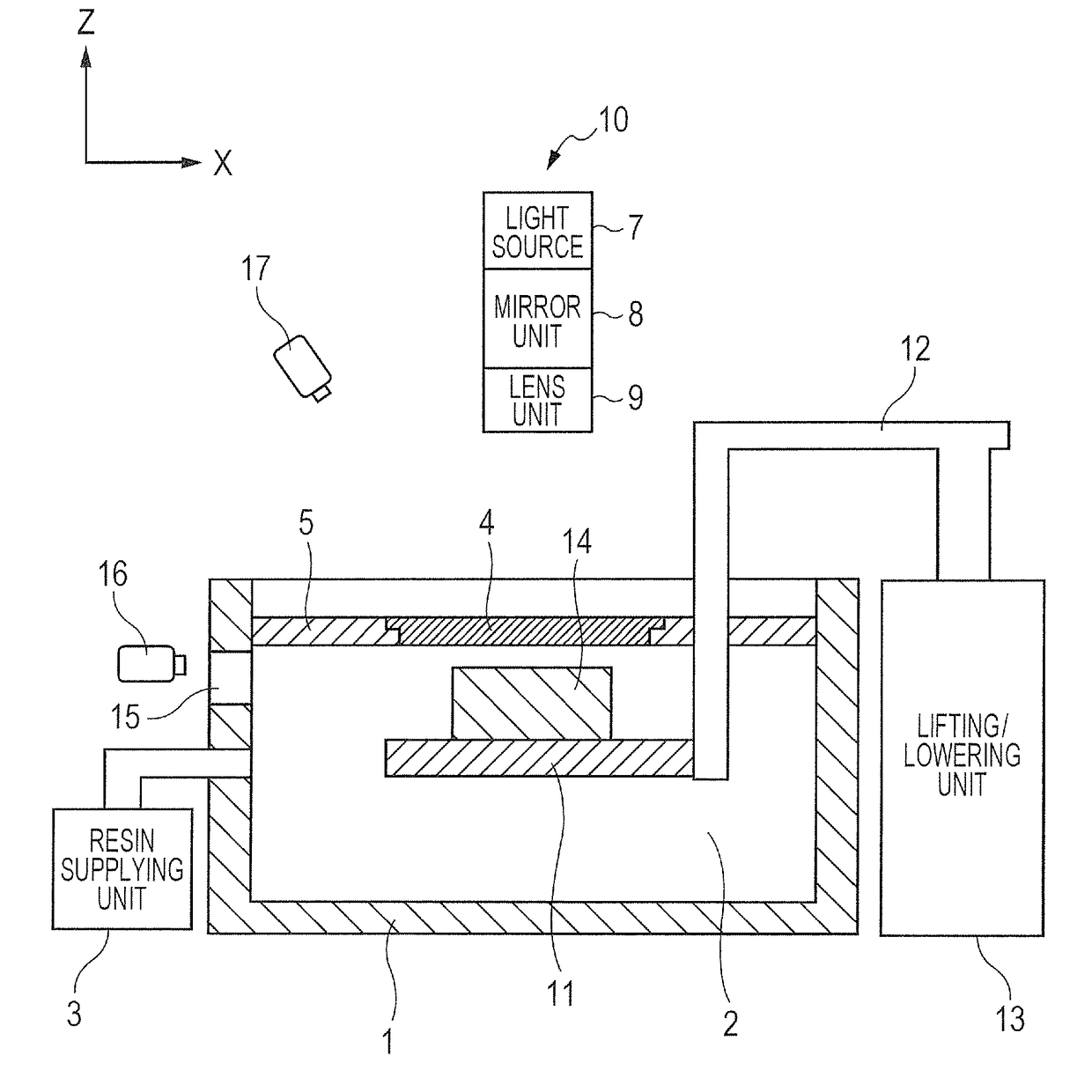
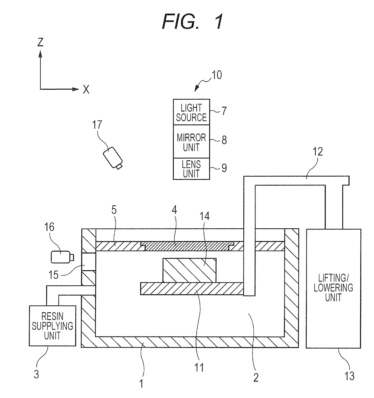
[0050]FIG. 1 is a schematic cross-section diagram for describing a constitution of a three-dimensional manufacturing apparatus according to the first embodiment of the present invention.

[0051](Constitution of Apparatus)

[0052]In FIG. 1, there are illustrated a container 1, a liquid photocurable resin 2, a resin supplying unit 3, a light transmission portion 4, a light shielding portion 5, a light source 7, a mirror unit 8, a lens unit 9, a light source unit 10, a base 11, a lifting / lowering arm 12, a lifting / lowering unit 13, a three-dimensional manufactured object 14, an observation portion 15, an infrared thermo-viewer 16, and an infrared thermometer 17.

[0053]The container 1, which is a container for holding the liquid photocurable resin 2, is formed of a material which blocks light of a wavelength region in which the liquid photocurable resin is cured or solidified.

[0054]The resin supplying unit 3 comprises a tank for storing the liquid photocurable resin and a pump, and supplies ...

second embodiment

[0142]FIGS. 9A to 9C are schematic cross-section diagrams for describing constitutions of the three-dimensional manufacturing apparatus according to the second embodiment of the present invention.

[0143]The apparatus of the first embodiment heats the light transmission portion by the transparent heater of generating heat by energization. However, the apparatus of the second embodiment is different from the apparatus of the first embodiment in which the light transmission portion is heated by an infrared heating device.

[0144](Constitution of Apparatus)

[0145]In FIGS. 9A to 9C, there are illustrated the container 1, the liquid photocurable resin 2, the resin supplying unit 3, the light source 7, the mirror unit 8, the lens unit 9, the light source unit 10, the base 11, the lifting / lowering arm 12, the lifting / lowering unit 13, three-dimensional manufactured object 14, the observation portion 15, and the infrared thermo-viewer 16.

[0146]Since the above constituent elements are the same as...

third embodiment

[0177]FIG. 9B is the schematic cross-section diagram of the apparatus for describing the constitution of the three-dimensional manufacturing apparatus according to the third embodiment of the present invention.

[0178]As well as the apparatus of the second embodiment, in the apparatus of the third embodiment, the light transmission portion is heated by the infrared heating device. However, the light transmission portion of the apparatus in the third embodiment is different from that in the second embodiment in the point that the light transmission portion transmits a gas such as oxygen or the like which inhibits curing of the photocurable resin.

[0179](Constitution of Apparatus)

[0180]In FIG. 9B, there are illustrated the container 1, the liquid photocurable resin 2, the resin supplying unit 3, the light source 7, the mirror unit 8, the lens unit 9, the light source unit 10, the base 11, the lifting / lowering arm 12, the lifting / lowering unit 13, the three-dimensional manufactured object...


PUM

PropertyMeasurementUnit
excitation frequencyaaaaaaaaaa
distanceaaaaaaaaaa
distanceaaaaaaaaaa

Abstract

There is provided a three-dimensional manufacturing apparatus which is characterized by comprising: a container configured to hold a liquid photocurable resin; a base configured to support a solid manufactured object obtained by curing the liquid photocurable resin; a moving unit configured to move the base; and a light source unit configured to irradiate light for curing the liquid photocurable resin. The container comprises a light transmission portion which is provided between the light source unit and the base, and is in contact with the liquid photocurable resin. The three-dimensional manufacturing apparatus further comprises a flow facilitating unit configured to facilitate a flow of the photocurable resin which is in contact with the light transmission portion, the flow being attended by the movement of the base.

Description

BACKGROUND OF THE INVENTIONField of the Invention[0001]The present invention relates to a three-dimensional manufacturing apparatus which produces a three-dimensional manufactured object by projecting an exposure image on a photocurable liquid resin material, a three-dimensional manufactured object producing method which produces the three-dimensional manufactured object, and a container which is used for the three-dimensional manufacturing apparatus.Description of the Related Art[0002]In recent years, expectations for a so-called three-dimensional printer are increasing. In particular, development of an apparatus which uses a method of producing a three-dimensional manufactured object by projecting an exposure image on a photocurable liquid resin material is vigorous.[0003]For example, in Japanese Patent Application Laid-Open No. H05-96632, there is disclosed an apparatus which contains a photocurable resin solution in a container of which the upper surface is opened, irradiates li...

Claims


Application Information

Patent Timeline
Patent Type & Authority Applications(United States)
IPC IPC(8): B29C64/264B29C64/129B29C64/371B29C64/255B33Y10/00B33Y30/00
CPCB29C64/264B29C64/129B29C64/371B29K2105/0058B33Y10/00B33Y30/00B29C64/255B29C64/135B29C64/205B29C64/124B29C64/295B33Y40/00B29C64/245
Inventor ARAI, TAKASHISEKINE, YASUHIROGENDA, HIDEO
Owner CANON KK
Why Eureka
Try Eureka