Flying car

a flying car and car body technology, applied in the field of flying cars, can solve the problems of rotors that are typically quite complex, require maintenance, and utilize mechanically complex systems to control both the collective and cyclic blade angles, and achieve the effects of convenient control, high compactness, and safety. high efficiency

Inactive Publication Date: 2018-03-08
BAROT AKASH GIRENDRA
View PDF2 Cites 12 Cited by
  • Summary
  • Abstract
  • Description
  • Claims
  • Application Information

AI Technical Summary

Benefits of technology

[0006]The personal flying car with a configuration that is safe, quiet, and efficient, as well as easy to control, highly compact, more like a modern days car and able to accomplish vertical takeoff and landing with transition of moving in any direction. In one embodiment, the flying car configuration includes multiple rotors oriented to provide vertical thrust for lift and control during takeoff, transition to and from forward, backward, left and right flight and landing. The rotors are attached to the quad-frame in fixed, non-planar orientations. The orientations of rotors provide lateral, fore and aft control of flying car without requiring a change of attitude, and minimize disturbances to the flow when the flying car is cruising. The rotors have forward, backwards, left, and right orientations, and are located on the corners of the flying car with one or more rotors located on each side.
[0007]The flying car has a place for 2 or more seats in the vehicle. The rotors provide lift and control during cruise, and one propeller provide forward, backward, left, right thrust. The combination of vertical lift bound the rotors, permitting movement in the flying car's center of gravity while still enabling the vehicle to maintain vertical flight control. The forward and rear rotors are also located to provide a boundary to avoid foreign object damage (FOD) to the lift rotors. The vertical lift rotors are arranged around the center of gravity, and the thrust of each rotor is adjustable, which permits the relocation of the center of lift in vertical flight if the center of gravity shifts.

Problems solved by technology

For the rotors to perform this dual function across a range of airspeeds, the rotors are typically quite complex.
Additionally, they utilize mechanically complex systems to control both the collective and cyclic blade angles.
Such rotors are mechanically complex and require maintenance.
Due to the multiple number and independence of the vertical lift rotors, the vertical thrust is redundant and thrust and control remain available even with the failure of any single rotor.

Method used


Image

  • Flying car
  • Flying car
  • Flying car

Examples


Embodiment Construction

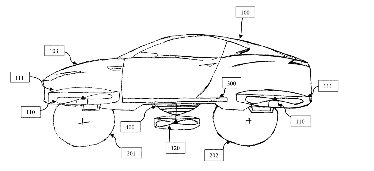
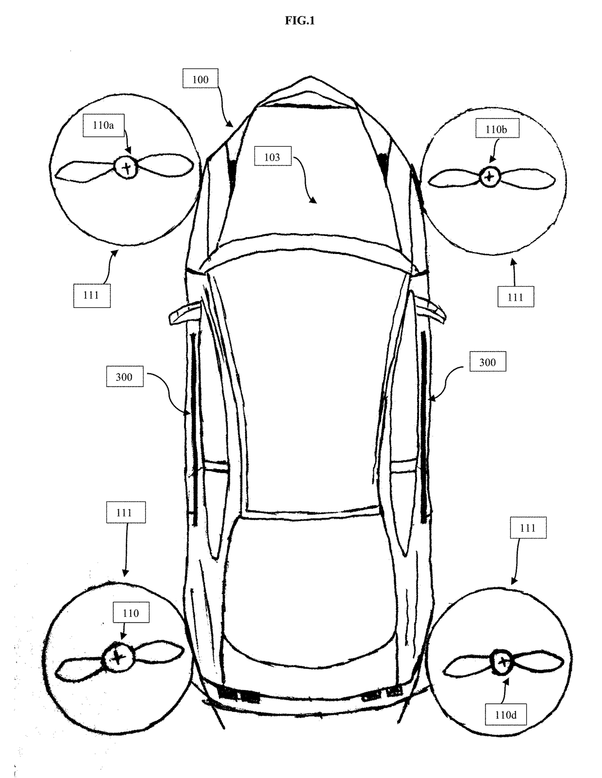
[0012]FIG. 1 illustrates a flying car 100 in accordance with one embodiment. Flying car 100 includes vertical lift rotor assemblies 110a and 110b and 110c and 110d (generally, 110) with fixed orientations; rotor fence 111; flight propellers 120 (not shown), a main body of the vehicle 103, a detachable battery 300 power source which is located inside the main body 103. Main body 103 also includes Tires (not shown), a computer to control inter mechanism of the vehicle (not shown), each of which is described further below.

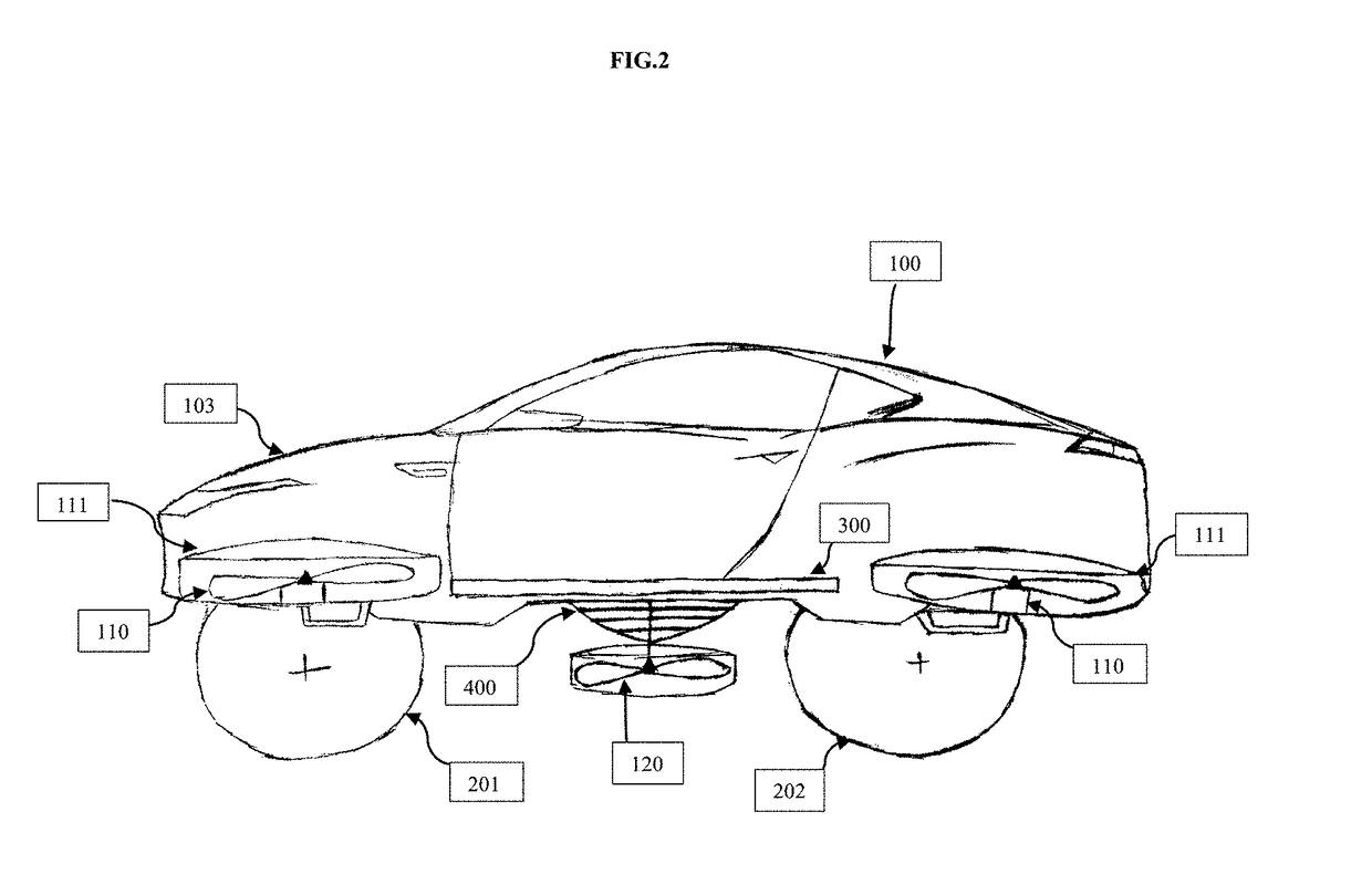
[0013]FIG. 2 illustrates a side view of flying car 100, including propeller 120; controller 400; detachable battery 300 power source; vertical lift rotor assemblies 110 and rotor fence 111; front tires 201 and rear tires 202. FIG. 3 illustrates a side view and a top view of the controller 400 whose one part will be inside the main body and the other part will be attached to the propeller 120.

[0014]In various embodiments, flying car 100 is sized to accommodate more tha...


PUM


Abstract

A safe, easy to control, efficient, and compact flying car configuration is enabled through the combination of multiple vertical lift rotors, and a thrust propellers which is placed on the center of lower frame of the vehicle. The vertical lift rotors, permits a balancing of the center of lift with the center of gravity for both vertical and horizontal flight whereas the propeller help to steer the vehicle in air. This multiple rotor system has the ability to tolerate a relatively large variation of the payload weight for hover, transition, or cruise flight while also providing vertical thrust redundancy. The passengers are safe inside the vehicle as the rotors and the propeller are surrounded by a thick frame around them. This rotors provide a controlled thrust for a specific lift range.

Description

BACKGROUND1. Field of the Invention[0001]This disclosure relates generally to a personal flying car configured to provide safe operations while achieving robust control. In particular, the flying car is a personal vehicle with vertical takeoff and landing capability, and that provides vertical and horizontal thrust in a controlled fashion for hover, transition and cruise flight. This vehicle is made to hover and in transit vertically within a specific altitude range.2. Description of Related Art[0002]A flying car is personal aircraft that provides door-to-door aerial transportation (e.g., from home to work or to the supermarket) as conveniently as a car.[0003]Taking off and landing vertically till it gets adequate lift, requires a flying car to provide vertical thrust. Thrust produced in the vertical direction provides lift to the vehicle and is able to control these forces in a balanced fashion.[0004]The quadcopter, is one common type of VTOL. Quadcopter have medium size rotors tha...

Claims


Application Information

Patent Timeline
Patent Type & Authority Applications(United States)
IPC IPC(8): B60F5/02B64C37/00B64C27/08B64C27/14
CPCB60F5/02B64C27/14B64C27/08B64C37/00
Inventor BAROT, AKASH GIRENDRA
Owner BAROT AKASH GIRENDRA
Why Eureka
Try Eureka