Frame assembly body and casing

a technology of frame and body, applied in the direction of dismountable cabinets, furniture parts, mechanical equipment, etc., can solve the problem of long repair time, and achieve the effect of convenient assembly and sufficient strength

Inactive Publication Date: 2018-03-08
MITSUBISHI ELECTRIC CORP
View PDF1 Cites 7 Cited by
  • Summary
  • Abstract
  • Description
  • Claims
  • Application Information

AI Technical Summary

Benefits of technology

[0011]According to the invention, the connected section in which the ends of the two frame materials are joined perpendicularly has: the projected piece locking section in which the slit-shaped fitting hole, the notch, or the recessed section formed in the second frame material is fitted to the projected piece provided in the first frame material; and the slit fitted section in which the slit-shaped notch formed in the second frame material is fitted to the fitting slit formed in the manner to notch the first frame material. Accordingly, the frame assembly body and a casing that can easily be assembled without welding work or a coupling member in a complicated shape for coupling the frame materials to each other, for which the number of fastening tools, such as a bolt or a rivet, is reduced, and that secure sufficient strength can be obtained.
[0012]A purpose, a characteristic, a perspective, and an effect of the invention other than those described above will become apparent from the

Problems solved by technology

However, the assembly of the structural object by welding leads to such problems that an assembly worker is limited to a license holder and that long time is required for repair work due to significant post-assembly deformation caused by welding.

Method used


Image

  • Frame assembly body and casing
  • Frame assembly body and casing
  • Frame assembly body and casing

Examples


first embodiment

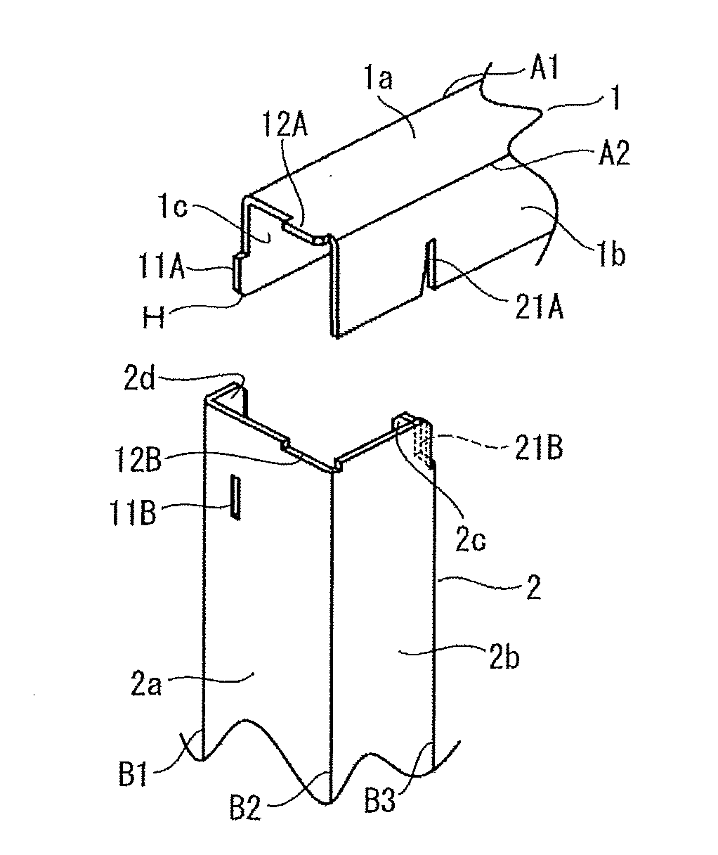
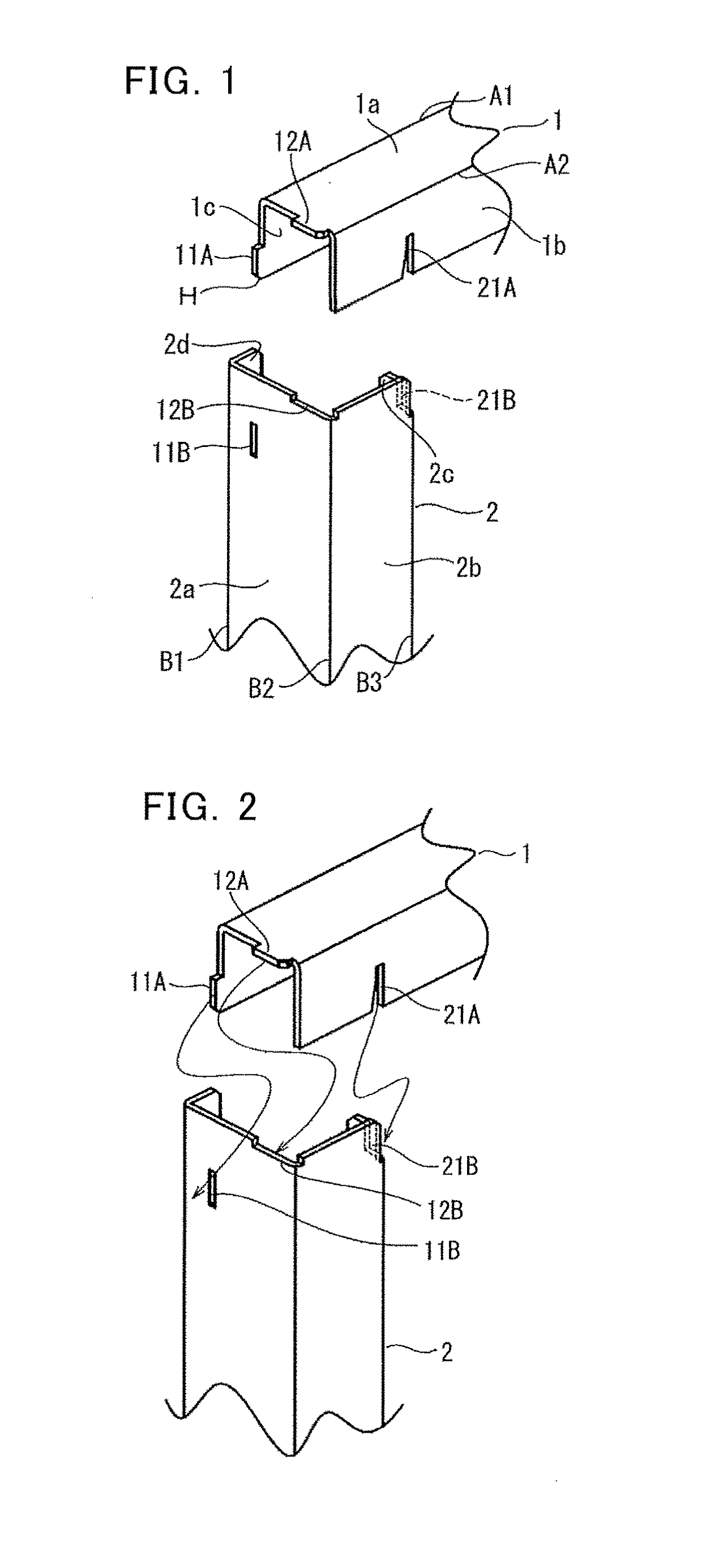
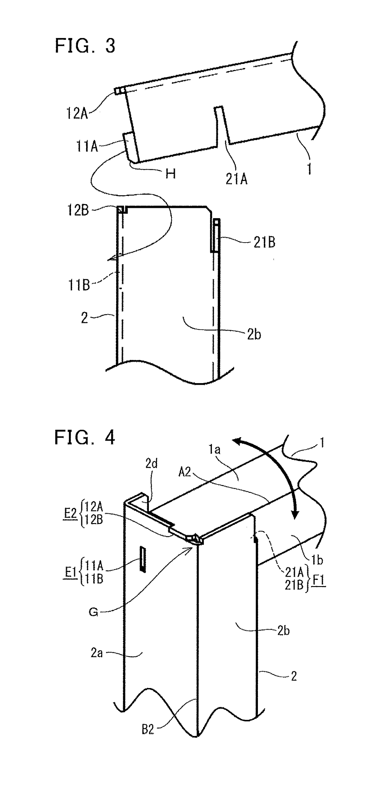
[0029]FIG. 1 is a perspective view of a projected piece and a fitting hole as well as a notch and a fitting slit provided in a connected section of two frame materials at a corner of a frame assembly body according to a first embodiment of the invention, FIG. 2 is a perspective view that illustrates fitting positions of the two frame materials to each other at a time when the two frame materials depicted in FIG. 1 are connected, and FIG. 3 is a side view that illustrates an operation at the time when the two frame materials depicted in FIG. 1 are connected. Note that, in this first embodiment, a description will be centered on a structure of the connected section constructed at a corner of a rectangle in the frame assembly body that includes a rectangular frame (framework) formed by joining ends of four frame materials perpendicularly. Note that the same or corresponding members or portions in each of the drawings are denoted by the same reference sign for the description.

[0030]A fr...

second embodiment

[0052]FIG. 6 is a perspective view of a projected piece locking section and a slit fitting section provided in a connected section of three frame materials at a corner of a frame assembly body according to a second embodiment of the invention, FIG. 7 is a perspective view that illustrates an operation at a time when the three frame materials depicted in FIG. 6 are connected, and FIG. 8 is a perspective view of a fixed state where a three-way connected section, in which the three frame materials depicted in FIG. 7 are connected, is fastened by screws. Note that this second embodiment differs from the first embodiment in a point that the three frame materials are fitted in the connected section at the corner of the frame assembly body in order to obtain a rectangular parallelepiped frame assembly body.

[0053]Note that a basic structure, in which the connected section is configured by fitting the frame material 1 in the lateral direction and the frame material 2 in the vertical directio...

third embodiment

[0063]FIG. 9 is a perspective view of a frame assembly body according to a third embodiment of the invention, and FIG. 10 is an exploded perspective view that illustrates an assembly procedure of the frame assembly body depicted in FIG. 9. FIG. 9 is a perspective view in which a frame structure 26 according to the third embodiment of the invention is seen obliquely from above. Note that four each of the frame material 1, the frame material 2, and the frame material 3 are used in this third embodiment, and this third embodiment relates to the frame assembly body constructed of a rectangular parallelepiped framework that is produced by using the three-way connected sections, for each of which plural locking means such as the projected piece, the fitting hole, the recessed section, the fitting slit, and the notch described in the second embodiment are used. In FIG. 9, when an arrow direction is set as a direction seen from front, the frame material 1, the frame material 2, and the fram...


PUM


Abstract

A frame assembly body includes a connected section in which one ends of first and second frame materials, each of which has plural bent sections and plural surfaces, are joined perpendicularly. The connected section has: a projected piece locking section in which a slit-shaped fitting hole, a notch, or a recessed section formed in the second frame material is fitted to a projected piece provided in the first frame material; and a slit fitted section in which a slit-shaped notch formed in the second frame material is fitted to a fitting slit formed in a manner to notch the first frame material.

Description

TECHNICAL FIELD[0001]The invention relates to a frame assembly body and a casing for which the frame assembly body is used, the frame assembly body being preferably used as a framework of the casing for a switchboard or the like, for example.BACKGROUND ART[0002]Conventionally, a structure of welding and joining ends of frame materials has widely been adopted for an assembly of a structural object with a hexahedral frame. However, the assembly of the structural object by welding leads to such problems that an assembly worker is limited to a license holder and that long time is required for repair work due to significant post-assembly deformation caused by welding. To handle these problems, a structure of adding a member that couples the frame materials to a corner of the hexahedral frame and fastening the frame materials by a bolt or a rivet to obtain required strength has been disclosed (for example, see PTL 1, 2). In addition, a structure of fastening the frame materials by the bol...

Claims


Application Information

Patent Timeline
Patent Type & Authority Applications(United States)
IPC IPC(8): F16B12/50H02B1/01H05K7/18
CPCF16B12/50H02B1/014H05K7/18A47B47/0058A47B47/027A47B96/14A47B96/1441H02B1/01
Inventor MATSUMOTO, TAKEMI
Owner MITSUBISHI ELECTRIC CORP
Why Eureka
Try Eureka