
Automated-vehicle 3D road-model and lane-marking definition system

a technology of automatic vehicles and road models, applied in television systems, instruments, image enhancement, etc., can solve problems such as insufficient accuracy of road models, and achieve the effect of accurate control of host vehicles and accurate estimation of pertinent features

Inactive Publication Date: 2018-03-08
APTIV TECH LTD
View PDF1 Cites 12 Cited by
  • Summary
  • Abstract
  • Description
  • Claims
  • Application Information

AI Technical Summary

Benefits of technology

The patent is about a system that uses lidar and a camera to create a 3D model of a road. This model takes into account the curved shape of the road and the lane markings, which helps to estimate things like the position of preceding vehicles and control the car in an autonomous driving setting. The technical effect of this system is to improve the accuracy of autonomous driving and to make it safer.

Problems solved by technology

Under these non-planar conditions, lane-marking estimates from a vision system that assumes a planar travel-surface leads to an inadequately accurate road-model.

Method used


Image

  • Automated-vehicle 3D road-model and lane-marking definition system
  • Automated-vehicle 3D road-model and lane-marking definition system
  • Automated-vehicle 3D road-model and lane-marking definition system

Examples


Embodiment Construction

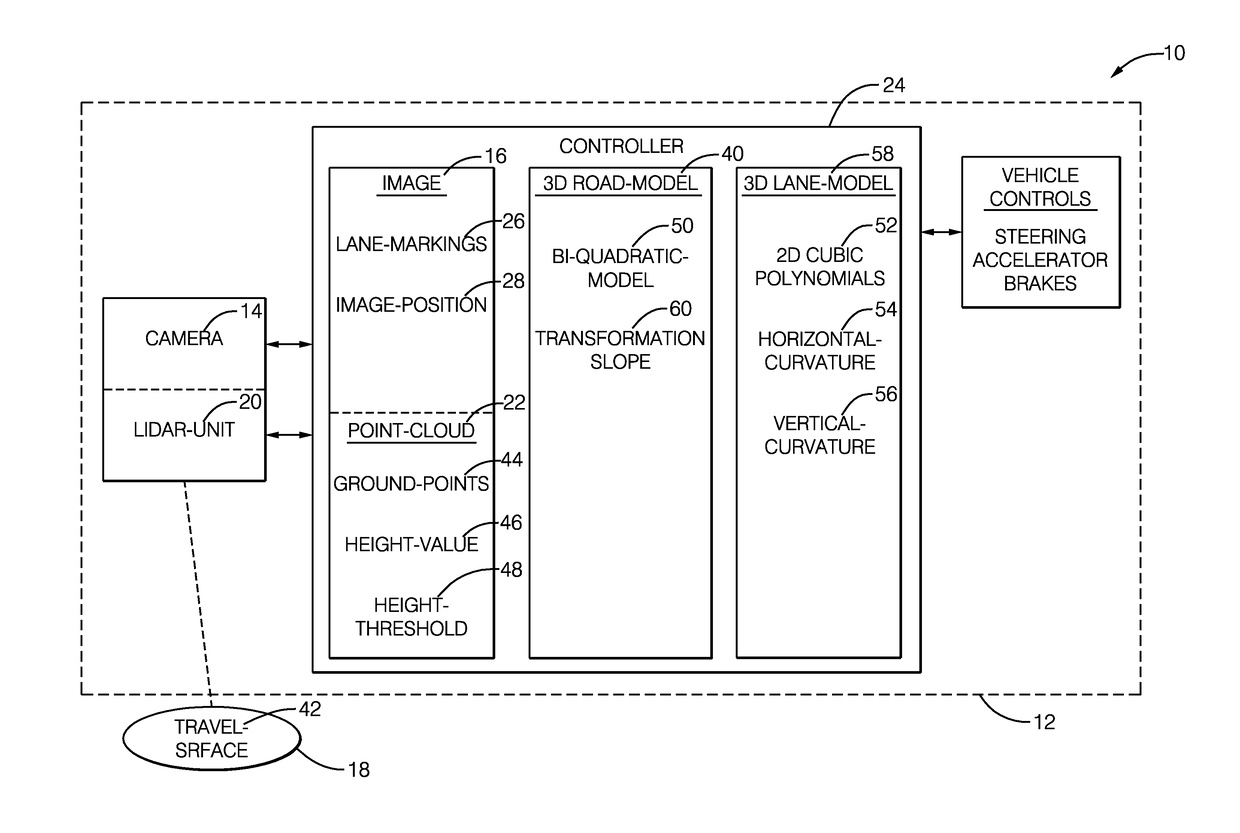
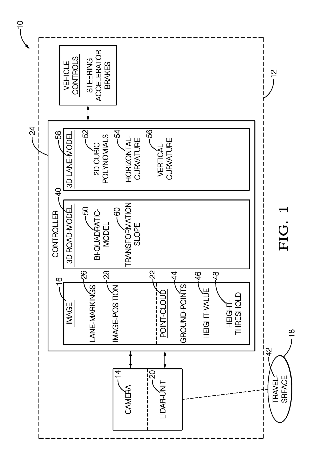
[0012]FIG. 1 illustrates a non-limiting example of a road-model-definition system 10, hereafter referred to as the system 10, which is suitable for use by an automated-vehicle, e.g. a host-vehicle 12. While the examples presented may be characterized as being generally directed to instances when the host-vehicle 12 is being operated in an automated-mode, i.e. a fully autonomous mode, where a human operator (not shown) of the host-vehicle 12 does little more than designate a destination to operate the host-vehicle 12, it is contemplated that the teachings presented herein are useful when the host-vehicle 12 is operated in a manual-mode. While in the manual-mode the degree or level of automation may be little more than providing steering assistance to the human operator who is generally in control of the steering, accelerator, and brakes of the host-vehicle 12. That is, the system 10 may only assist the human operator as needed to keep the host-vehicle 12 centered in a travel-lane, ma...


PUM


Abstract

A road-model-definition system suitable for an automated-vehicle includes a camera, a lidar-unit, and a controller. The camera used is to provide an image of an area proximate to a host-vehicle. The lidar-unit is used to provide a point-cloud descriptive of the area. The controller is in communication with the camera and the lidar-unit. The controller is configured to determine an image-position of a lane-marking in the image, select ground-points from the point-cloud indicative of a travel-surface, determine coefficients of a three-dimensional (3D) road-model based on the ground-points, and determine a transformation to map the lane-marking in the image onto the travel-surface based on the image-position of a lane-marking and the 3D road-model and thereby obtain a 3D marking-model.

Description

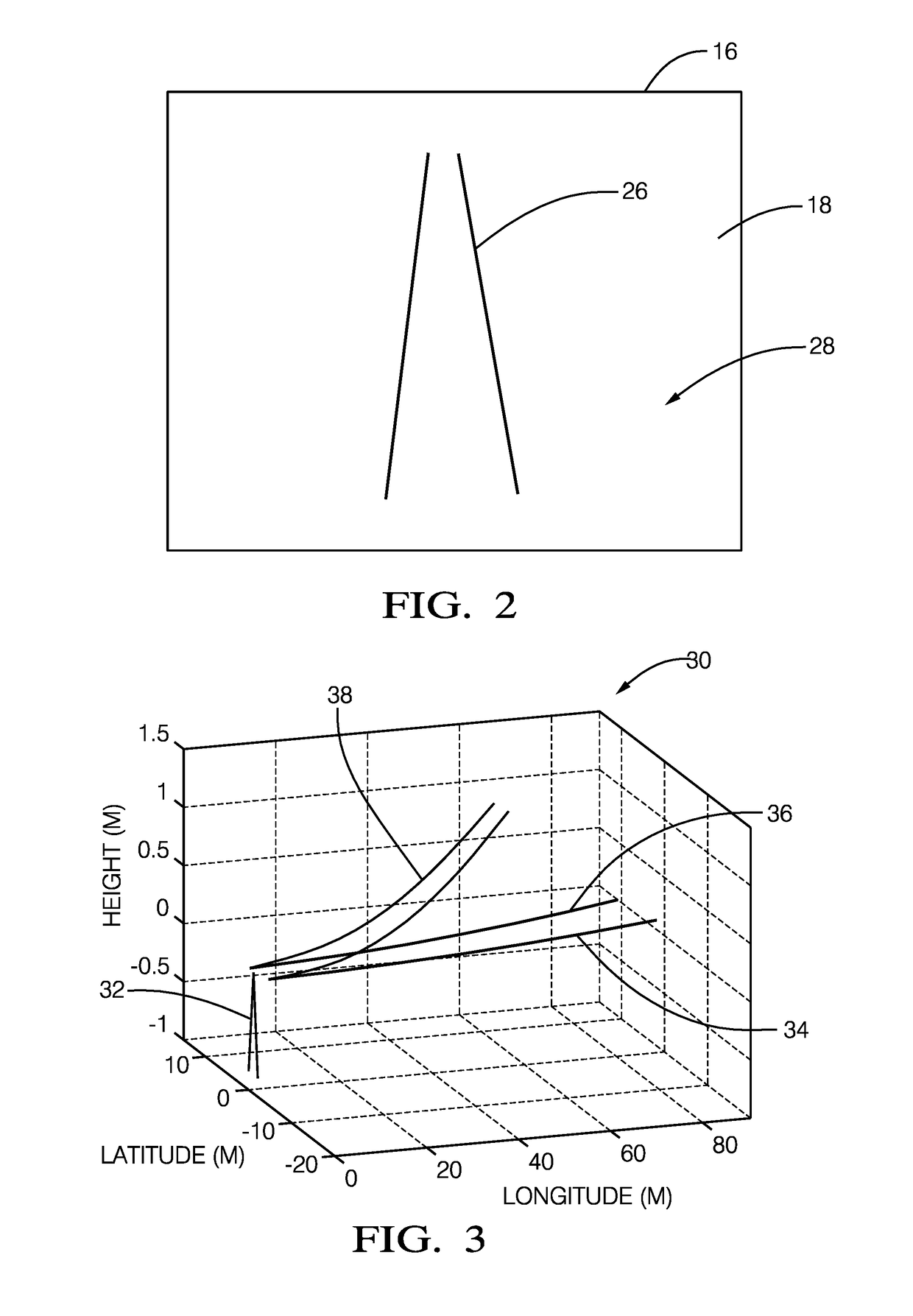
TECHNICAL FIELD OF INVENTION[0001]This disclosure generally relates to a road-model-definition system, and more particularly relates to a system that determines a transformation used to map a lane-marking present in an image from a camera onto a travel-surface model that is based on lidar data to obtain a 3D marking-model of the lane-marking.BACKGROUND OF INVENTION[0002]An accurate model of the upcoming travel-surface (e.g. a roadway) in front of a host-vehicle is needed for good performance of various systems used in automated vehicles including, for example, an autonomous vehicle. It is known to model lane-markings of a travel-surface under the assumption that the travel-surface is planar, i.e. flat and level. However, the travel-surface is actually frequently crowned, meaning that the elevation of the travel-surface decreases toward the road-edge which is good for drainage during rainy conditions. Also, there is frequently a vertical curvature component which is related to the ch...

Claims


Application Information

Patent Timeline
Patent Type & Authority Applications(United States)
IPC IPC(8): G05D1/02G05D1/00G06F17/50G06K9/00G06T7/00H04N7/18G01S17/89G01S17/931
CPCG05D1/0231G05D1/0088G06F17/5009G06T2207/10028G06T7/004H04N7/183G06K9/00798G01S17/42G06T17/00G06T19/20G01S17/89G01S7/4802G06T7/70G01S17/931G06V20/588G06V2201/12G06F30/20
Inventor SCHIFFMANN, JAN K.SCHWARTZ, DAVID A.
Owner APTIV TECH LTD
Learn More