
Pressing input device

a technology of input device and input button, which is applied in the direction of contact fixed to the operating part, electrical apparatus, electric switch, etc., can solve the problems of limiting the inclined operation of the operating body, lack of return mechanism, and high probability of rattle and rattle nois

Active Publication Date: 2018-03-08
ALPS ALPINE CO LTD
View PDF5 Cites 0 Cited by
  • Summary
  • Abstract
  • Description
  • Claims
  • Application Information

AI Technical Summary

Benefits of technology

The pressing input device described in this patent allows for easier operation compared to devices where the operational body is directly pressed. However, the longer a distance by which the leaf string is pressed, the more the leaf spring is warped, leading to a larger elastic reaction force and increased operation load. To reduce the operation load, the leaf string needs to be elongated which makes it difficult to downsize the device.

Problems solved by technology

This restricts the inclined operation of the operational body when the operational body is pushed by the drive lever.
However, the structure described in Japanese Unexamined Patent Application Publication No. 2006-92996 lacks a return mechanism that returns the drive lever to its initial orientation as a single component.
This is problematic in that the drive lever causes a rattle and rattle noise is likely to occur.
Another problem with the structure is that the elastic force of a return spring that protrudes the operational body from the case is used to rotate the drive lever to return it toward its initial orientation, so if a load exerted on the rotational fulcrum of the drive lever is increased, a load used to protrude the operational body from the case becomes excessive, lowering reliability in the operation of the operational body.
In this structure, however, the longer a distance by which the leaf string is pressed is, the more the leaf spring is warped and the larger elastic reaction force becomes.
This increases the operation load.
As a result, it becomes difficult to downsize the pressing input device.

Method used


Image

  • Pressing input device
  • Pressing input device
  • Pressing input device

Examples


first embodiment

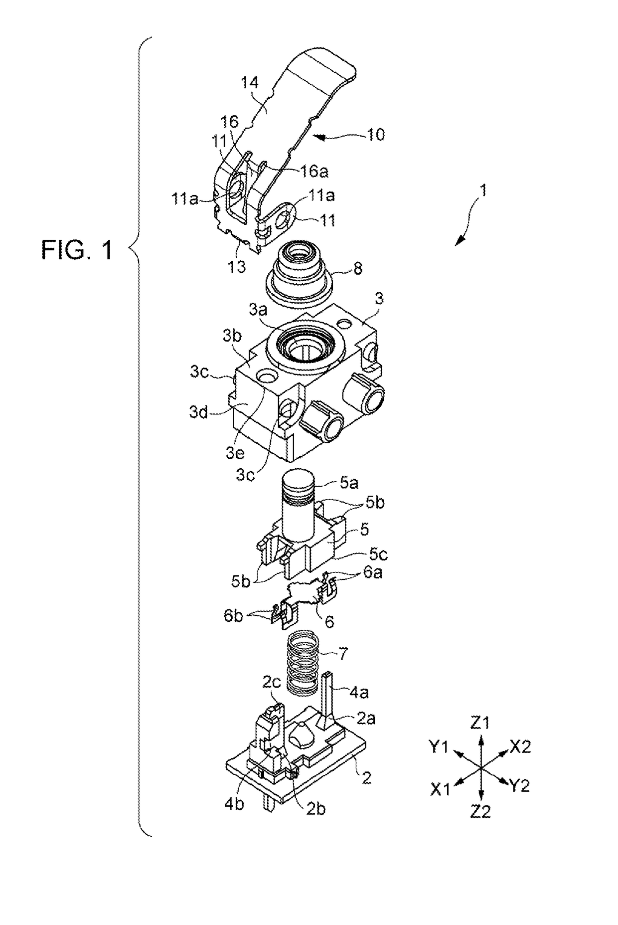
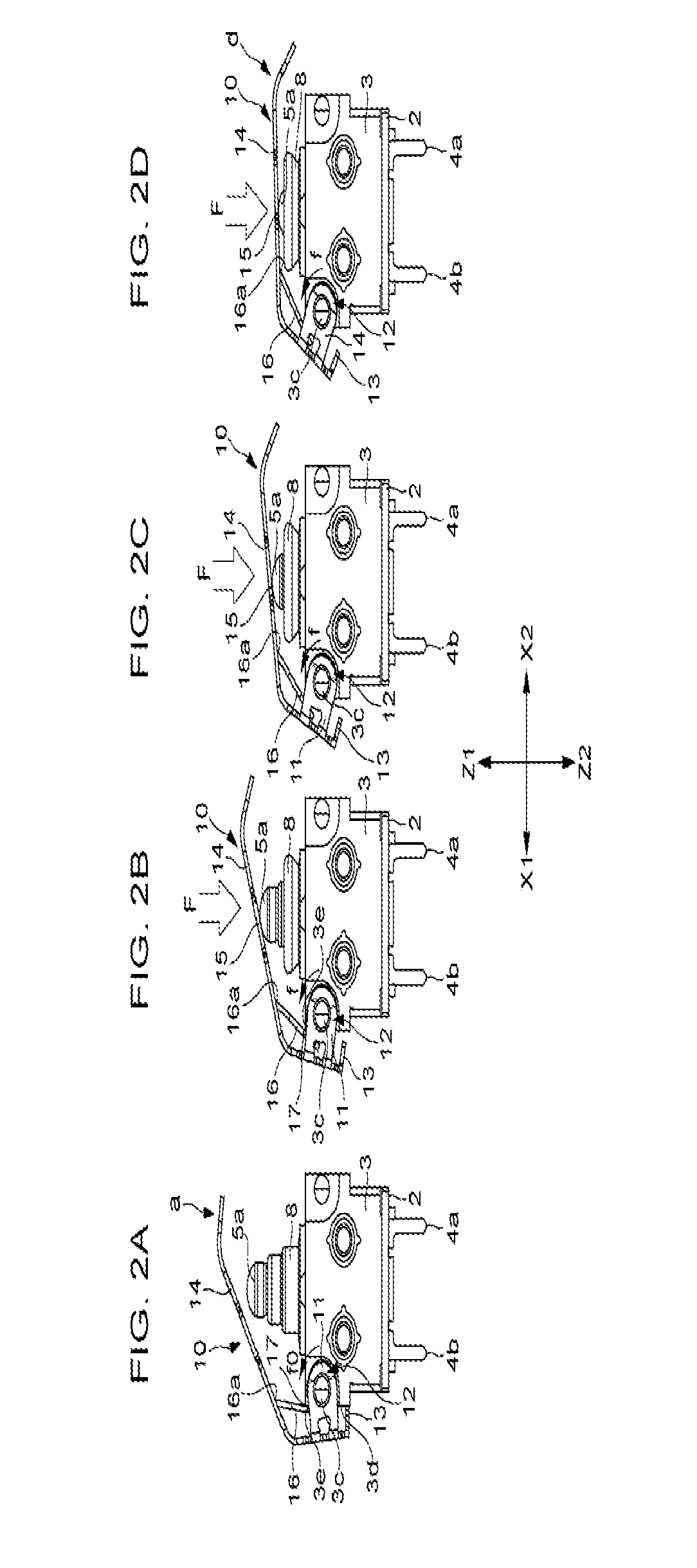
[0037]With the pressing input device 1 in the first embodiment, the rotational return force f generated by the warp of the spring piece 16 does not become excessive even when the drive arm 10 swings clockwise and the drive arm 10 does not give an excessive operational reaction force even when the drive arm 10 swings as illustrated in FIGS. 2B to 2D in succession in that order. An amount by which the spring piece 16 warps when the drive arm 10 swings clockwise is small, so even if the free length of the spring piece 16 is short, excessive stress is not exerted on the spring piece 16 and the fatigue of the spring piece 16 can be reduced. Even if the spring piece 16 is short, an appropriate rotational return force f can be given to the spring piece 16 and its fatigue can be reduced, so the drive arm 10 can be downsized and the pressing input device 1 can thereby be downsized.

[0038]How the spring piece 16 is warped will be described below in details.

[0039]FIG. 3 illustrates an operation...

second embodiment

[0053]FIG. 8 illustrates part of a pressing input device 101 in the present invention.

[0054]With this pressing input device 101, a deformed part is formed at the top end of a spring piece 116 that is bent from the operational piece 14 of the drive arm 10 and extends. The deformed part abuts the upper surface 3b of the case 3, forming a contact part 117. When the drive arm 10 swings from the initial orientation “a” to the completely swung orientation “d”, the top end of the spring piece 116 preferably slides on the upper surface 3b of the case 3, shifting the position of the contact part 117 between the spring piece 116 and the upper surface 3b in the X1-X2 direction.

[0055]With this pressing input device 101 as well, the contact part 117 is preferably positioned closer to the linkage part 12 than the bend bottom end 116a of the spring piece 116 is, and the bend bottom end 116a moves on an arc path Φ that has a radius R and also has the center O at the linkage part 12. Therefore, when...


PUM


Abstract

A spring piece is formed integrally as part of a drive arm that presses an operational body. The spring piece is disposed between a pressing part at which the drive arm presses the operational body and a linkage part that acts a swinging fulcrum. A contact part between the spring piece and a case is positioned closer to the linkage part than the bend bottom end is. When the drive arm swings from an initial orientation to a completely swung orientation, the spring piece can generate an elastic return force. The elastic return force does not largely increase even when the drive arm swings.

Description

CLAIM OF PRIORITY[0001]This application claims benefit of priority to Japanese Patent Application No. 2016-173992 filed on Sep. 6, 2016, which is hereby incorporated by reference in its entirety.BACKGROUND1. Field of the Disclosure[0002]The present disclosure relates to a pressing input device that operates an operational body by swinging a drive arm to change the state of an electrically variable part such as a switch.2. Description of the Related Art[0003]Japanese Unexamined Patent Application Publication No. 2006-92996 describes an arrangement related to a pressing input device (lever driven electrical component). This pressing input device includes, in a case, an operational body that can advance and retreat, a sliding member that is driven by being pushed by the operational body, and a detecting member to which an electric signal is output due to the operation of a sliding member. A drive lever is swingably supported by the case. When an external force is applied to the drive l...

Claims


Application Information

Patent Timeline
IPC IPC(8): H01H21/24H01H21/12
CPCH01H21/24H01H2205/002H01H2235/01H01H21/12H01H13/186H01H21/285
Inventor TANAKA, TAKAKISUGAWARA, TATSUO
Owner ALPS ALPINE CO LTD
Learn More