Posture vehicle

a technology of vehicle body and body, applied in the field of electric vehicles, can solve the problems of poor balance experience, difficult to keep the vehicle body stable, and difficult to actually operate and control the user, and achieve the effect of low induction sensitivity

Active Publication Date: 2018-03-15
SHENZHEN DYNAMIC BALANCE TECH CO LTD
View PDF30 Cites 17 Cited by
  • Summary
  • Abstract
  • Description
  • Claims
  • Application Information

AI Technical Summary

Benefits of technology

[0005]In conclusion, the purpose of embodiments of the present invention is to provide an posture vehicle, in order to overcome problems o

Problems solved by technology

However, the control pedal can only move along with the vehicle body but fails to move relative to the vehicle body, so induction sensitivity is low, causing that actual operation

Method used


Image

  • Posture vehicle
  • Posture vehicle
  • Posture vehicle

Examples


embodiment 1

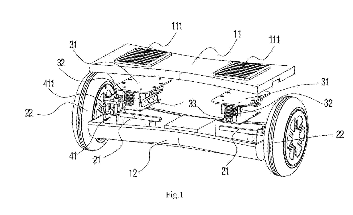
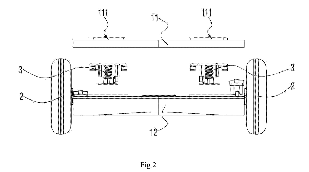
[0032]By referring to FIG. 1, FIG. 2 and FIG. 3, a posture vehicle provided in embodiments of the present invention comprises a vehicle body 1, two wheels 2 pivoted to the vehicle body 1, pedals 111 installed on the vehicle body 1, and two driving components 3, installed in the vehicle body 1, to drive the two wheels 2 to rotate with the movement of the pedals 111. Each wheel 2 comprises a stator fixing shaft 21 pivoted to the vehicle body 1 and a rotor-driven wheel 22 connected to the stator fixing shaft 21. Each of the two driving components 3 is electrically connected to its respective rotor-driven wheel 22. Two driving components 3 are installed in the vehicle body 1 at an interval in parallel and are respectively fixed and connected to the stator fixing shafts 21 corresponding to the rotor-driven wheels 22. When there is an inclined angle generated between each driving component 3 and a horizontal plane, a driving signal is output to the corresponding rotor-driven wheel 22 so t...

embodiment 2

[0039]By referring to FIG. 5, the posture vehicle provided in the present embodiment is similar to that in embodiment 1. The differences are that in the present embodiment:[0040]the two rotor-driven wheels 22′ are installed in the vehicle body 1′, and present an acute angle between each wheels. Two driving components 3′ are respectively located at outer sides of the two rotor-driven wheels 22′. Namely, a spacing between upper ends of the two rotor-driven wheels 22′ is larger than a spacing between lower ends of the two rotor-driven wheels 22′. In this way, a spacing between the two rotor-driven wheels 22′ is reduced so that a turning radius of the posture vehicle is smaller, which enables the vehicle suitable for travel in a narrow space.

[0041]Contents not described in the present embodiment are the same as those of embodiment 1, and are not repeated herein.

embodiment 3

[0042]By referring to FIG. 6, FIG. 6 is a stereoscopic structural schematic diagram of an posture vehicle 500 provided in the present embodiment. The posture vehicle 500 comprises a vehicle body 510, motors, supporting shafts 530 and driving components 540. The motors can adopt inner rotor motors, and can also adopt outer rotor motors. In the present embodiment, the motors are the outer rotor motors, and specifically are hub motors 520. Wheel bodies 521 are connected to rotors of the hub motors 520. Two hub motors 520 are respectively installed on the left side and the right side of the vehicle body 510. Two supporting shafts 530 are coaxially connected with stators of the two hub motors 520 respectively. The supporting shafts 530 are also simultaneously connected with the vehicle body 510 rotatably. In this way, the vehicle body can rotate relative to the hub motors 520. Two driving components 540 are installed in the vehicle body 510. One driving component 540 is located on the le...


PUM


Abstract

The present invention relates to the technical field of electric vehicles, and provides an posture vehicle, which comprises a vehicle body, two wheelers pivoted to the vehicle body, pedals installed on the vehicle body, and two driving components installed in the vehicle body and driving the two wheelers to rotate driven by the pedals. The driving components and the wheelers are in the same operating plane. Namely, in a using process, the user treads on the wheelers, thereby eliminating interference of a balance state of the vehicle body to an output signal of the driving components, and enhancing the sensitivity of the driving components for judging the balance signal.

Description

CROSS REFERENCE TO RELATED APPLICATIONS[0001]The application claims priority to a Chinese patent application with application number of 201610749689.7 and titled as “posture vehicle” filed on Aug. 29, 2016 to Patent Office of the People's Republic of China, disclosures of which are incorporated herein by reference in their entireties.TECHNICAL FIELD[0002]The present invention relates to the technical field of electric vehicles, and more specifically, to a posture vehicle.BACKGROUND[0003]A posture vehicle is also called as a motion sensing vehicle or an electric personal assistive mobility device. The posture vehicle has an operation principle as follows: change of an posture of a vehicle body is detected by using a gyroscope and an acceleration sensor inside the vehicle body; and a motor is accurately driven by using a servo control system to ensure balance of the vehicle body.[0004]At present, a control mode of the posture vehicle is as follows: a control pedal is installed on a pe...

Claims


Application Information

Patent Timeline
IPC IPC(8): B62K11/00
CPCB62K11/007A63C17/014A63C17/12A63C2203/12A63C2203/52B62K3/002B62K23/08A63C2203/18
Inventor LI, LIFANG
Owner SHENZHEN DYNAMIC BALANCE TECH CO LTD
Why Eureka
Try Eureka