Floor tile with vibration and shock control

a technology of vibration control and floor tiles, applied in resiliently mounted floors, flooring, other domestic articles, etc., can solve the problems of low-frequency vibration and structure-borne sound, noise generation and vibration in noise-sensitive rooms, and floor surfaces in such facilities are subject to a considerable amount of hard use, and achieves easy tunable sound dampening properties, a great flexibility in the manufacture of tiles, and a more rigid

Inactive Publication Date: 2018-03-15
REGUPOL AMERICA
View PDF6 Cites 14 Cited by
  • Summary
  • Abstract
  • Description
  • Claims
  • Application Information

AI Technical Summary

Benefits of technology

[0007]An object is to provide a floor, floor panel or floor tile provides a low natural frequency in response to dynamic impacts, caused by rhythmic stepping, running, treadmills and other equipment.
[0017]An embodiment is directed to a method of making a floor tile with shock and vibration control. The method includes: positioning a preformed second sound dampening layer in a mold; pouring a backing mixture into the mold; positioning a preformed first sound dampening layer in a mold; pouring an intermediate layer into a mold; positioning a preformed top layer in the mold; applying pressure to the second sound dampening layer, the backing mixture, first sound dampening layer, the intermediate layer and the preformed top layer to form the floor tile; and extracting the floor tile from the mold. The preformed second sound dampening layer reduces the demolding time required to remove the floor tile from the mold.

Problems solved by technology

However, running on treadmills, rhythmic stepping, dropping weights accidentally or slamming weights intentionally on the floor results in low-frequency vibration and structure-borne sound, which may transmit into the building structure and generate unwanted noise and vibration in noise-sensitive rooms and areas in the building complex.
The floor surfaces in such facilities are subject to a considerable amount of hard use.
These surfaces or tiles provide little or no vibration and / or shock control, resulting in the low-frequency vibration and structure-borne sound being transmitted through the structure.
The transmission of sound through the structure has a detrimental effect on the location of the facilities and the level and quality of the activities being performed in the facilities.

Method used


Image

  • Floor tile with vibration and shock control
  • Floor tile with vibration and shock control
  • Floor tile with vibration and shock control

Examples


Embodiment Construction

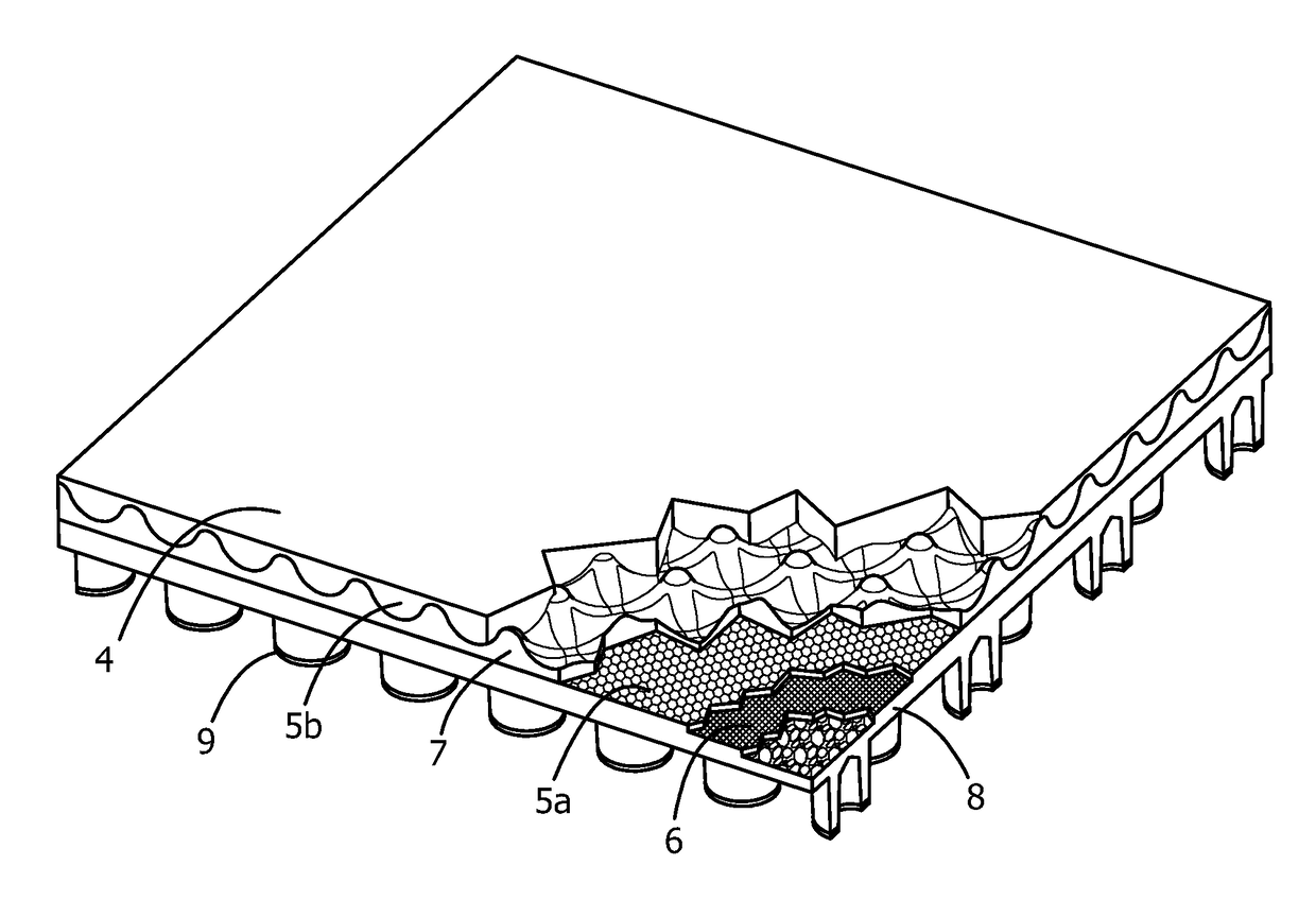
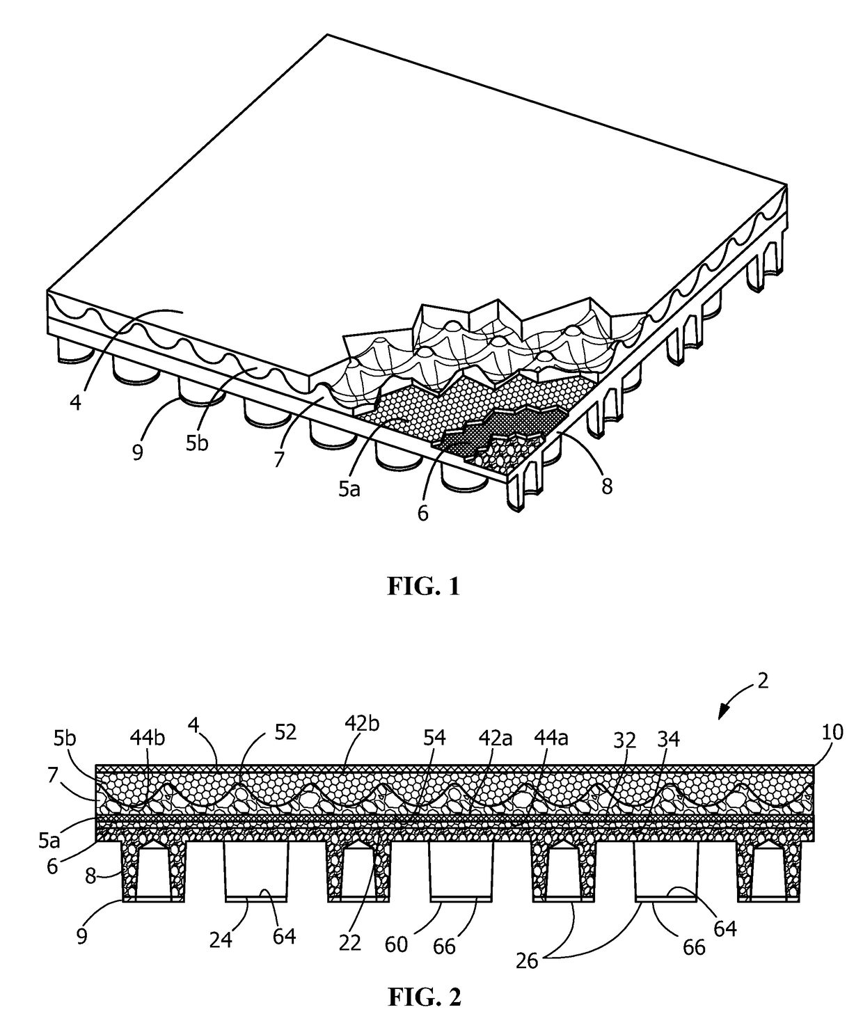
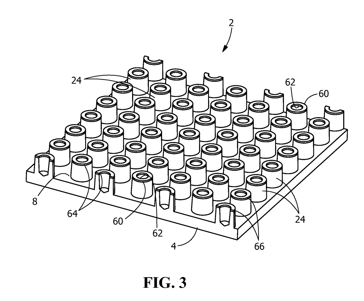
[0023]The description of illustrative embodiments according to principles of the present invention is intended to be read in connection with the accompanying drawings, which are to be considered part of the entire written description. In the description of embodiments of the invention disclosed herein, any reference to direction or orientation is merely intended for convenience of description and is not intended in any way to limit the scope of the present invention. Relative terms such as “lower,”“upper,”“horizontal,”“vertical,”“above,”“below,”“up,”“down,”“top” and “bottom” as well as derivative thereof (e.g., “horizontally,”“downwardly,”“upwardly,” etc.) should be construed to refer to the orientation as then described or as shown in the drawing under discussion. These relative terms are for convenience of description only and do not require that the apparatus be constructed or operated in a particular orientation unless explicitly indicated as such. Terms such as “attached,”“affi...


PUM

PropertyMeasurementUnit
densityaaaaaaaaaa
densityaaaaaaaaaa
thicknessaaaaaaaaaa

Abstract

A floor panel with shock and vibration control and method of manufacture. A first sound dampening layer is positioned between a top layer and a bottom layer of the floor panel. The first sound dampening layer has a series of hills and valleys and is made of material which provides a low natural frequency in response to a dynamic impact and transforms energy into heat in response to a high energy impact. The second sound dampening layer extends from the bottom layer in a direction away from the top layer. The second sound dampening layer is a plurality of preformed rings. The first sound dampening layer and the second sound dampening layer reduce the amount of energy transferred from the floor panel to a structure on which the floor panel is positioned.

Description

CROSS-REFERENCE TO RELATED APPLICATIONS[0001]This application is a Continuation-in-Part of U.S. patent application Ser. No. 15 / 491,338 filed on Apr. 19, 2017, which is a Continuation-in-Part of U.S. patent application Ser. No. 15 / 265,146 filed on Sep. 14, 2016, and claims priority to those applications, which are herein incorporated by reference in their entirety.FIELD OF THE INVENTION[0002]This invention relates generally to a floor tile for shock and vibration control and a method of manufacture. In particular, the invention is directed to an acoustic floor tile which controls noise and vibration while providing a dynamic stiffness to provide a stable platform.BACKGROUND OF THE INVENTION[0003]Health and fitness clubs have become part of the modern life as well as the modern architecture. From hotels and apartment complexes, to commercial mixed-use buildings, to corporate offices, to multi-purpose sports facilities—many of these have dedicated rooms and areas for fitness, cardio an...

Claims


Application Information

Patent Timeline
Patent Type & Authority Applications(United States)
IPC IPC(8): E04F15/22E04F15/02E04F15/10B32B7/02
CPCE04F15/225E04F15/02177E04F15/107B32B2419/04B32B2307/56B32B2307/102B32B7/02E04F2290/044E04F15/105E04F15/22E04F2290/043B29L2031/732B29C43/18B29C2043/185B29C2043/189B32B3/02B32B3/26B32B3/28B32B3/30B32B3/08B32B5/028B32B5/16B32B25/10B32B5/26B32B5/30B32B25/047B32B2250/05B32B25/16B32B25/14B32B2260/021B32B2260/025B32B2260/046B32B2262/0207B32B2262/101B32B2262/14B32B2264/0207B32B2270/00B32B2307/546B32B2307/10B32B2307/732B32B2307/72B32B2307/734B32B2307/402B32B2607/00
Inventor HAINBACH, DIRKSASSMANNSHAUSEN, FLORIAN
Owner REGUPOL AMERICA
Why Eureka
Try Eureka