
Method of Laying Lined Pipeline

Active Publication Date: 2018-03-15
PIONEER LINING TECH
View PDF0 Cites 2 Cited by
  • Summary
  • Abstract
  • Description
  • Claims
  • Application Information

AI Technical Summary

Benefits of technology

The patent text explains how to maintain the proper shape and size of a liner used in a well. This is done by ensuring that there are no breaks or gaps between the different sections of the liner. This helps to keep the liner secure and prevents any leaks or damage during use.

Problems solved by technology

However, during the reversion process, the varying geometry of the inner diameter of the host pipe and the influence of any internal weld bead protrusions, surface irregularities and the like, may interfere with the reversion process, causing it to be uneven.
In these circumstances, it is possible that air pockets may be trapped in the annular space between the outer surface of the liner pipe and the inner surface of the host pipe.
This is considered to present a potential operational risk that the liner pipe may collapse during operation of, say, a flowline which comprises lined pipeline.
It is also considered to present a potential operational risk during initial laying of the lined pipeline—to the extent that it may not be considered safe to lay lined pipeline on the seabed using conventional methods.

Method used


Image

  • Method of Laying Lined Pipeline
  • Method of Laying Lined Pipeline
  • Method of Laying Lined Pipeline

Examples


Embodiment Construction

[0037]As discussed in the background to the invention above, there are potential risks associated with the laying of lined pipeline on the seabed. An embodiment of the present invention is illustrated in FIGS. 1 to 6 which reduces these risks and increases the integrity and reliability of the process and of the resulting lined pipeline in service.

[0038]As explained in the background to the invention, the life and performance of new and existing pipelines can be extended and optimised by lining lengths of metal pipe with polymer liners. Techniques such as the Applicant's Swagelining® pipe lining service allows existing pipelines to be remediated and new pipelines to be provided with corrosion resistance by installing a polymer liner that remains in tight contact with the inside of a host pipe.

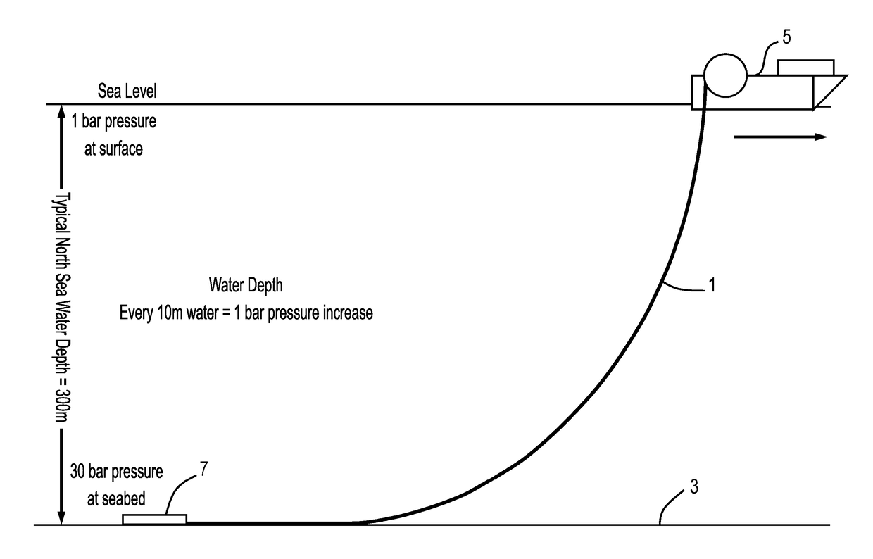
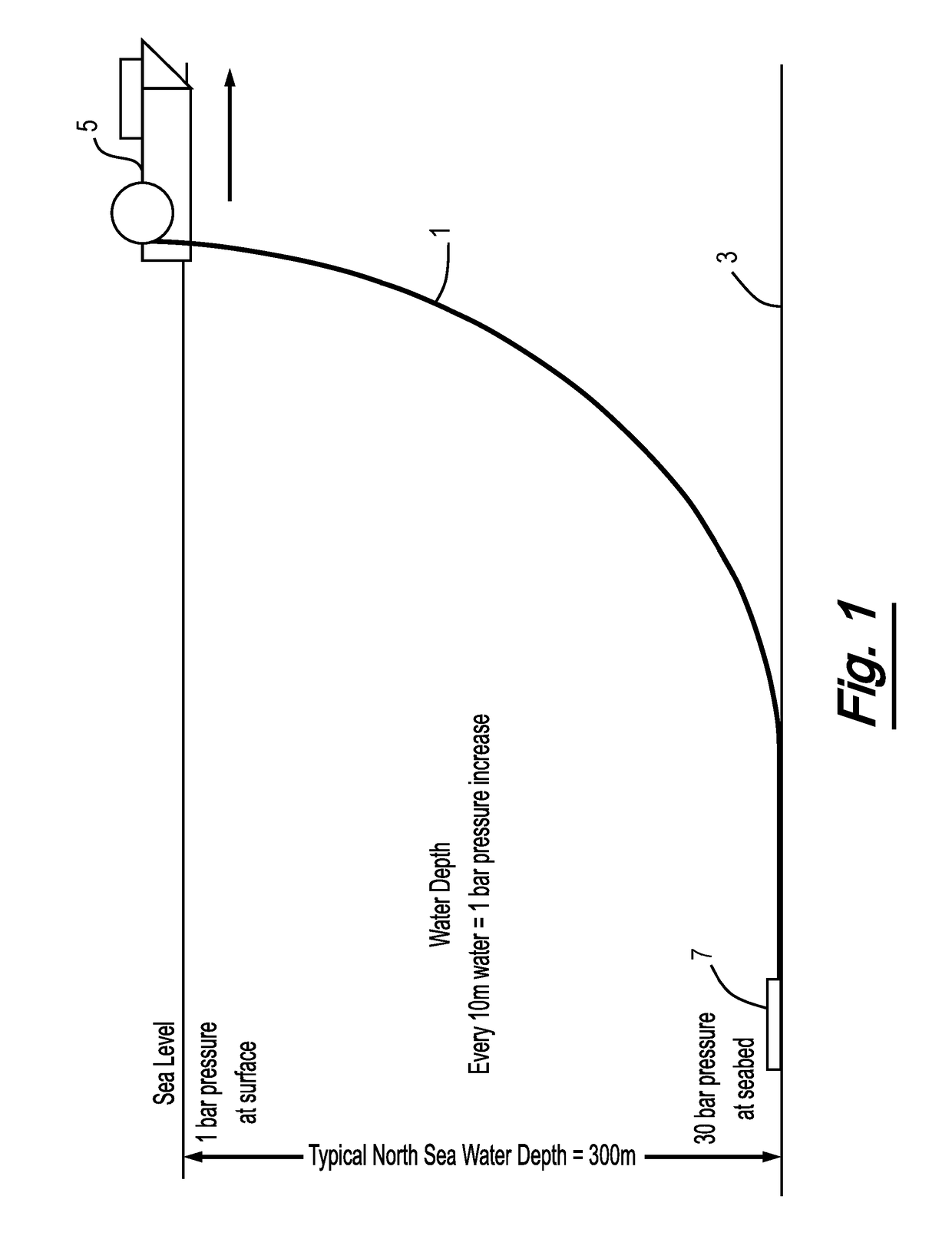
[0039]FIG. 1 illustrates a pipelay operation about to commence, in which a polymer lined pipeline 1 is to be laid on the seabed 3 by a reel lay vessel 5 at a typical North Sea water depth of 300...


PUM

PropertyMeasurementUnit
Pressureaaaaaaaaaa
Diameteraaaaaaaaaa
Lengthaaaaaaaaaa

Abstract

A method lays lined pipeline which actively and successfully removes air pockets which night be trapped in the annulus between the liner and the host pipe by progressively flooding the lined pipeline. Further, the liner is brought into closer contact and engagement with the host pipe. The removal of air in the annulus enables the pipeline test pressure to stabilize more quickly and avoids the risk of potential collapse during operational service life in the event the pipeline pressures fluctuate or a vacuum is created during an emergency shutdown.

Description

[0001]The present invention relates to methods of laying pipe on the seabed. More specifically, the present invention concerns improvements to methods of laying lined pipeline that increases the integrity and reliability of the process and of the resulting lined pipeline in service.BACKGROUND TO THE INVENTION[0002]The life and performance of new and existing pipelines can be extended and optimised by lining lengths of metal pipe with polymer liners. Prior to their insertion in a host pipe, polymer liner pipes have a larger outer diameter than the inner diameter of the host pipe into which they are being inserted. The liner pipes are temporarily reduced in diameter immediately prior to insertion, for example by pulling them through the host pipe via a reduction die. After the insertion of the liner pipe is completed, the pulling tension is released and the liner pipe is allowed to revert towards its original size so as to provide a tight fitting liner inside the host pipe.[0003]Howev...

Claims


Application Information

Patent Timeline
IPC IPC(8): F16L1/16B63B35/03F16L1/26F16L1/18F16L1/19F16L58/10F16L58/18
CPCF16L1/163B63B35/03F16L1/26F16L1/18F16L1/19F16L58/1009F16L58/181F16L58/1036F16L55/1652F16L1/16F16L1/165
Inventor BARNES, STEPHEN
Owner PIONEER LINING TECH
Learn More