Method and apparatus for bandwidth selection for radar transmission

a bandwidth selection and radar technology, applied in the field of radar bandwidth selection for radar transmission, can solve the problems of degrading the performance of the radar system, affecting the performance of the affecting the performance of the weather radar and the next generation air traffic control radar, so as to achieve the effect of optimizing the transmission of radar

Active Publication Date: 2018-03-15
US SEC THE ARMY THE
View PDF1 Cites 3 Cited by
  • Summary
  • Abstract
  • Description
  • Claims
  • Application Information

AI Technical Summary

Benefits of technology

[0010]The present invention provides a method for optimizing radar transmissions by balancing the conflicting objectives of high SINR and minimization of the range resolution cell size.

Problems solved by technology

The ever-growing wireless communications industry poses several challenges for radar systems.
One serious challenge is that RF interference caused by communication systems operating out-of-band to the radar degrades the performance of the radar system.
For example, out-of-band transmissions generated by base station transmitters are known to interfere with next generation weather radars as well as air traffic control radars.
Radar systems are further challenged by the potential new FCC regulations which are designed to ensure that every American has access to broadband capability.
However, any radar currently operating in the affected frequency bands will be rendered useless unless the radar has the capability to mitigate in-band radio frequency interference and cooperate with the communication systems.
However, the presence of ambient / remote RF transmissions within the radar band degrades the radar system and thus the performance of the radar system.

Method used


Image

  • Method and apparatus for bandwidth selection for radar transmission
  • Method and apparatus for bandwidth selection for radar transmission
  • Method and apparatus for bandwidth selection for radar transmission

Examples


Embodiment Construction

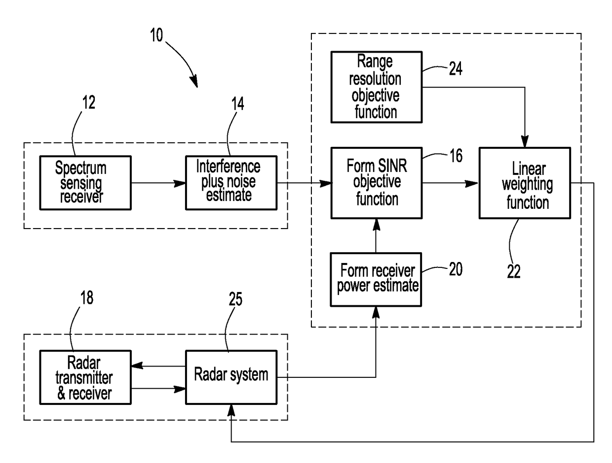
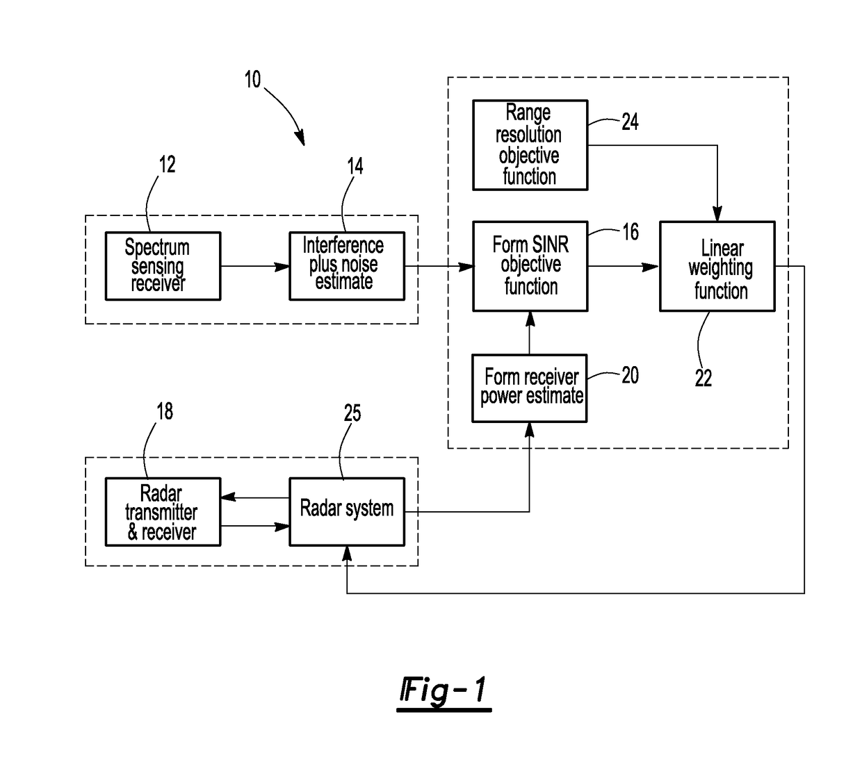
[0017]With reference first to FIG. 1, a block diagram of a radar installation 10 for performing the method of the present invention is illustrated. The system 10 includes a spectrum sensing receiver 12 which generates power samples to an interference plus noise estimator 14 over the frequency range for the desired radar transmission. The interference plus noise estimator 14 generates a plurality of output signals for a plurality of sub-bands within the frequency range in a fashion that will be subsequently described in greater detail. The output from the estimator 14 is coupled as an input to a form signal to interference plus noise objective function block 16. This signal to interference plus noise objective function block 16 calculates a signal to interference plus noise ratio or energy level for each sub-band.

[0018]The installation 10 further includes a radar transmitter and receiver 18 which is conventional in construction. The radar 18 and 25 provides an output signal to a form...


PUM


Abstract

A method for optimizing bandwidth selection of a radar transmission in a frequency bandwidth in which the frequency bandwidth is divided into a plurality of sub-bands having a plurality of different bandwidths. The energy level is measured for each sub-band and a range resolution is also determined for each sub-band. Thereafter, a sub-band is selected in the frequency range where the signal to interference plus noise ratio plus the range resolution is maximum. Thereafter, a radar transmission is transmitted in the selected sub-band with a bandwidth corresponding to the bandwidth of the selected sub-band.

Description

CROSS REFERENCE TO RELATED APPLICATIONS[0001]This application claims the benefit of U.S. provisional patent application Ser. No. 62 / 073,053 filed Oct. 31, 2014 which is herein incorporated by reference.GOVERNMENT INTEREST[0002]The invention described herein may be manufactured, used, and licensed by or for the United States Government.BACKGROUND OF THE INVENTIONI. Field of the Invention[0003]The present invention relates to a method for bandwidth selection for a radar transmission.II. Description of Related Art[0004]The ever-growing wireless communications industry poses several challenges for radar systems. One serious challenge is that RF interference caused by communication systems operating out-of-band to the radar degrades the performance of the radar system. For example, out-of-band transmissions generated by base station transmitters are known to interfere with next generation weather radars as well as air traffic control radars.[0005]Radar systems are further challenged by t...

Claims


Application Information

Patent Timeline
Patent Type & Authority Applications(United States)
IPC IPC(8): G01S7/02H04W16/14
CPCG01S7/023H04W16/14H04L5/0062G01S7/282G01S7/40G01S13/26
Inventor MARTONE, ANTHONY F.RANNEY, KENNETH I.DOGARU, TRAIAN V.SHERBONDY, KELLY D.
Owner US SEC THE ARMY THE
Why Eureka
Try Eureka