Solid-state image capturing apparatus and electric information device

a technology of solid-state image and electric information device, which is applied in the direction of radio frequency controlled devices, instruments, television systems, etc., can solve the problems of reducing the dynamic range and the light receiving sensitivity, and achieve the effect of reducing size, reducing light receiving sensitivity, and increasing pixel density

Inactive Publication Date: 2009-01-29
SHARP KK
View PDF2 Cites 0 Cited by
  • Summary
  • Abstract
  • Description
  • Claims
  • Application Information

AI Technical Summary

Benefits of technology

[0025]As described above, the reducing in size and providing higher pixel density are strongly desired for the conventional solid-state image capturing apparatus 100, and the cell size of the solid-state image capturing apparatus 100 needs to be reduced by minimizing the light receiving section 104 and the vertical charge transfer register 105. However, openings (openings above the light receiving section 104) of a shading film covering the vertical transfer electrode becomes narrow if the cell size is minimized, causing the decrease in light receiving sensitivity and the decrease in dynamic range.
[0026]It is said for the solid-state image capturing apparatus 110 that the light receiving sections 104a and 104b are arranged on either side of a vertical charge transfer register 105 and the light receiving sections 104a and 104b are repeatedly arranged in parallel to each other so that it is feasible to minimize the area of the vertical charge transfer register 105 and increase the area of the respective light receiving sections 104a and 104b, thereby preventing the light receiving sensitivity of the respective light receiving sections 104 and the dynamic range from decreasing.

Problems solved by technology

However, openings (openings above the light receiving section 104) of a shading film covering the vertical transfer electrode becomes narrow if the cell size is minimized, causing the decrease in light receiving sensitivity and the decrease in dynamic range.

Method used


Image

  • Solid-state image capturing apparatus and electric information device
  • Solid-state image capturing apparatus and electric information device
  • Solid-state image capturing apparatus and electric information device

Examples


Embodiment Construction

[0092]Hereinafter, an embodiment of a solid-state image capturing apparatus according to the present invention will be described with reference to figures. Note that the solid-state image capturing apparatus according to the embodiment has am image capturing section 101, a horizontal charge transfer register section 102 and an output section 103 (electric charge detection section), similar to the conventional solid-state image capturing apparatus 100 shown in FIG. 8, and the overall structures of these sections are the same as the conventional structures.

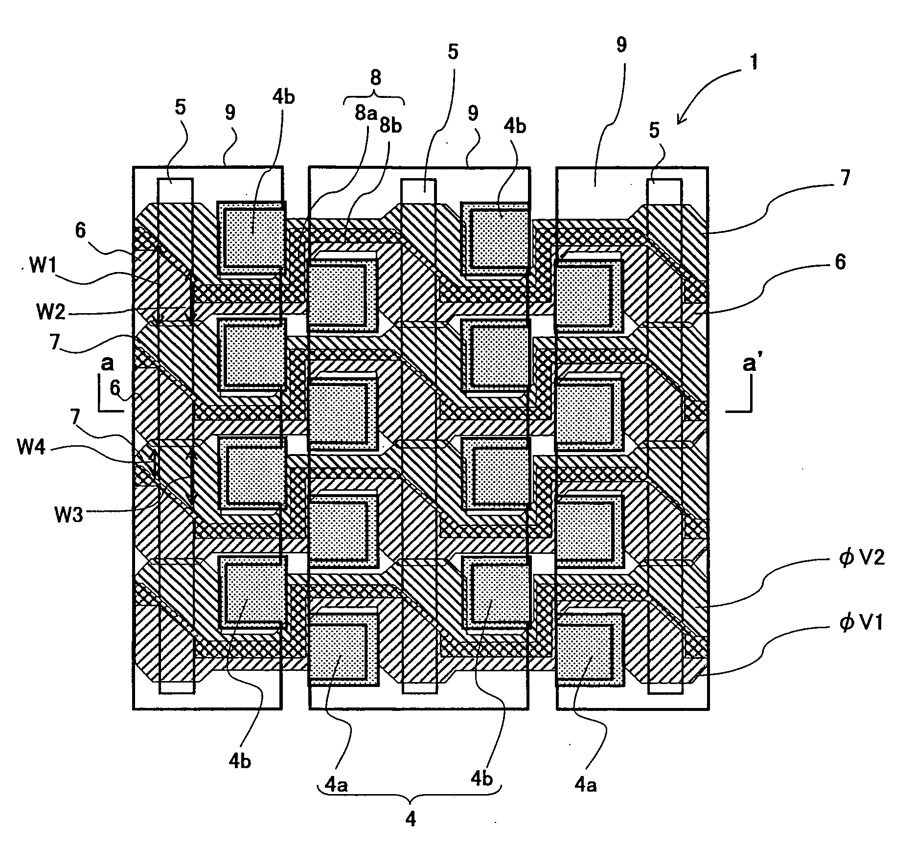
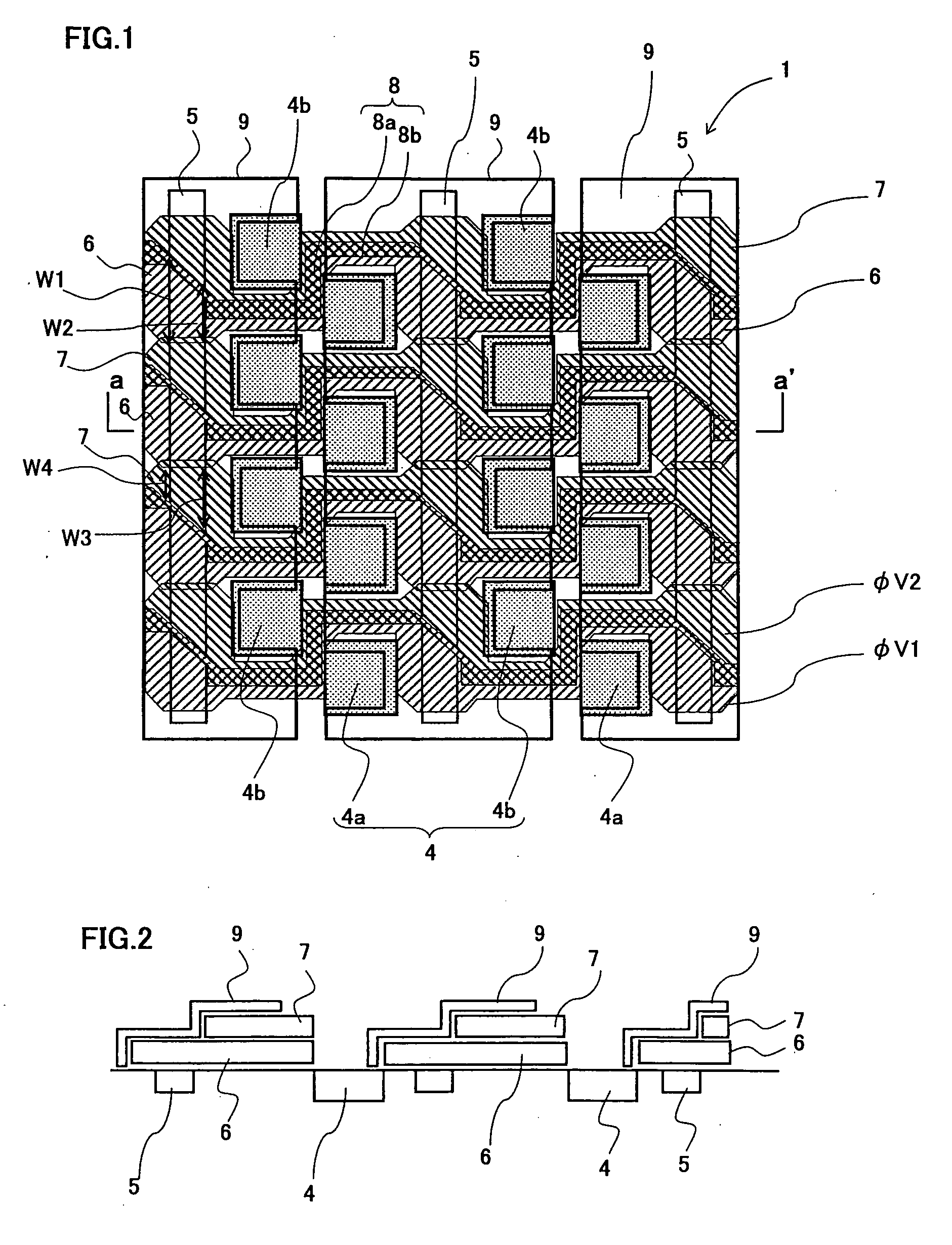
[0093]FIG. 1 is a top view showing an exemplary essential structure of an image capturing section in the solid-state image capturing apparatus according to the embodiment of the present invention. FIG. 2 is a longitudinal cross sectional view along the line a-a′ in FIG. 1.

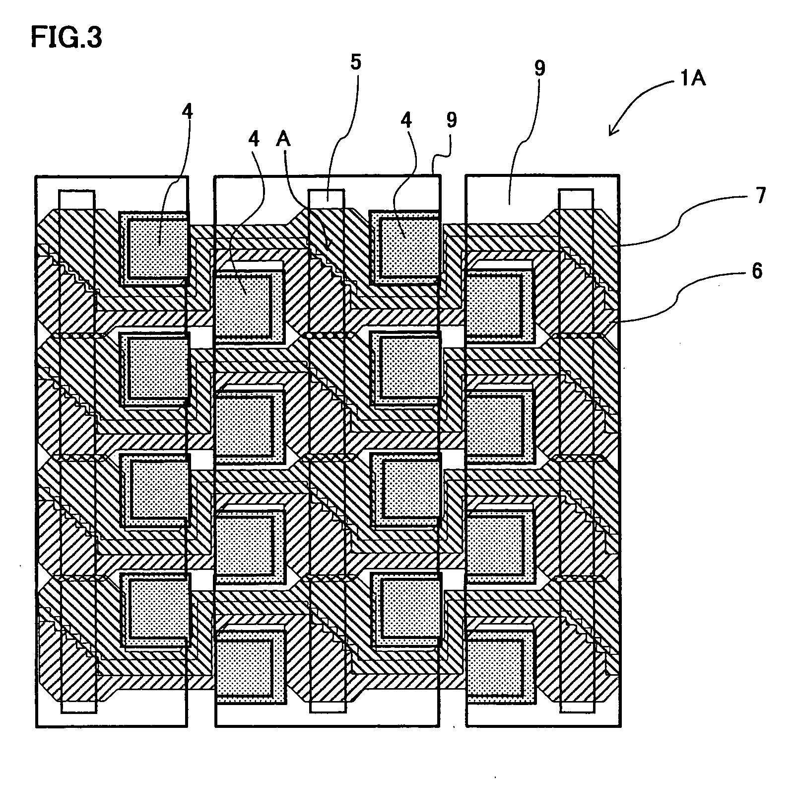
[0094]As shown in FIG. 1, on a semiconductor substrate, an image capturing section 1 of the solid-state image capturing apparatus according to the embodiment of th...


PUM


Abstract

A solid-state image capturing apparatus has a plurality of light receiving sections for performing photoelectric conversion on incident light to generate a signal charge, a charge transfer section provided along a light receiving section arranged in a column direction among the plurality of light receiving sections, for transferring signal charges generated in the light receiving section arranged in the column direction to a predetermined direction, and at least two layers of charge transfer electrodes provided on the charge transfer section via an insulation film, where a plane view width readable from the light receiving section is 50% to the whole edge of the edge of the light receiving section on the charge transfer section side.

Description

[0001]This Nonprovisional application claims priority under 35 U.S.C. §119(a) on Patent Application No. 2007-170726 filed in Japan on Jun. 28, 2007, the entire contents of which are hereby incorporated by reference.BACKGROUND OF THE INVENTION[0002]1. Field of the Invention[0003]The present invention relates to a solid-state image capturing apparatus having semiconductor devices for performing photoelectric conversion on image light from a subject to capture the same, and more particularly, to a solid-state image capturing apparatus suitable for minimizing a cell size, and an electronic information device, such as a digital camera (e.g., digital video camera and digital still camera), an image input camera, a scanner, a facsimile machine and a camera-equipped cell phone device, having the solid-state image capturing apparatus as an image input device in an image capturing section of the electronic information device.[0004]2. Description of the Related Art[0005]In recent years, solid-...

Claims


Application Information

Patent Timeline
Patent Type & Authority Applications(United States)
IPC IPC(8): H04N5/335H01L27/148H04N5/369H04N5/3728
CPCH01L27/14812H01L27/14831H01L27/14818H01L27/14806H04N25/00
Inventor NAKASHIMA, YOSHIMITSU
Owner SHARP KK
Why Eureka
Try Eureka