Degauss circuit for use in an electronically actuated door lock

a technology of degauss circuit and electromagnet, which is applied in the field of electromagnets, can solve the problems of inherently fail-safe direct pull electromagnetic locks, failure-secure locking devices, and inability to maintain magnetic properties,

Active Publication Date: 2018-03-15
HANCHETT ENTRY SYST
View PDF3 Cites 11 Cited by
  • Summary
  • Abstract
  • Description
  • Claims
  • Application Information

AI Technical Summary

Benefits of technology

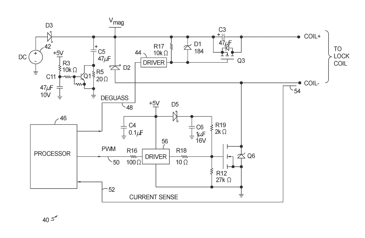
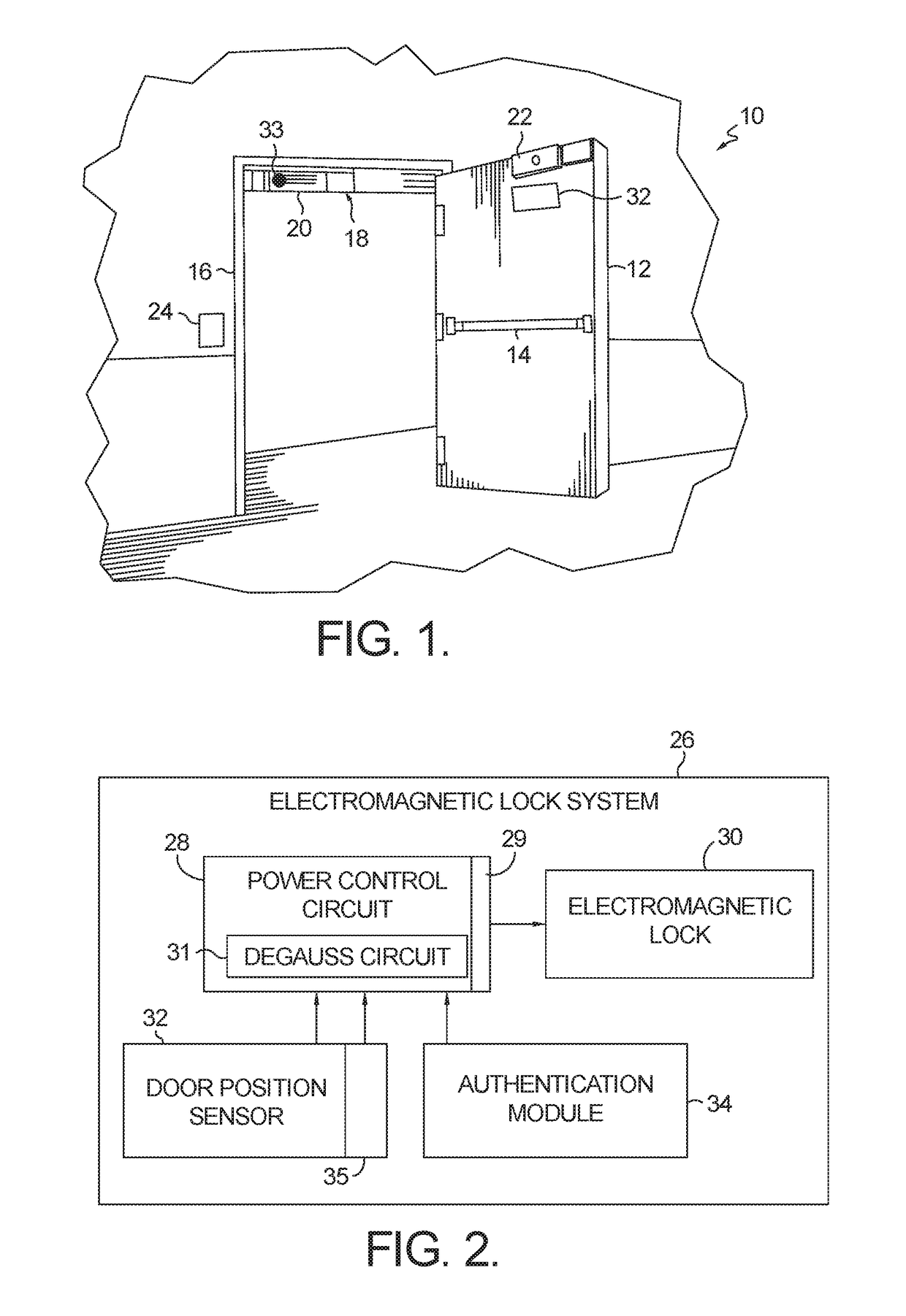
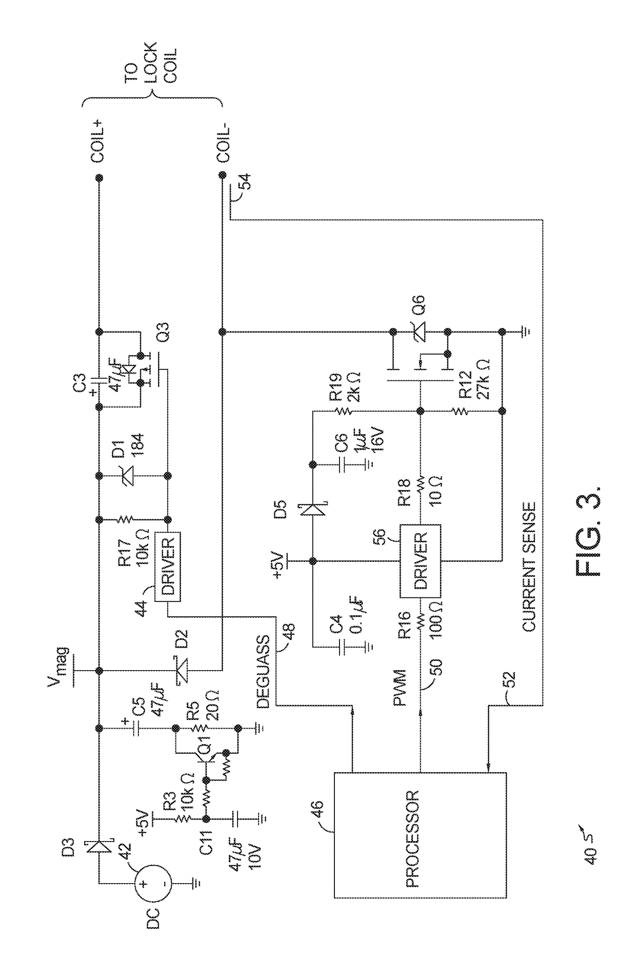
[0008]The present invention concerns a degauss circuit for use with electromagnetic door locks. The door lock circuit is configured to provide a constant current to the electromagnetic coil load. A pulse width modulation (PWM) controller varies the frequency and / or duty cycle to a switch in series with the coil. Coil current feedback is used to adjust the PWM frequency and / or duty cycle so as to maintain the current through the coil at a certain level to maintain a desired holding force on the door lock. A degauss circuit in-line with the current flowing through the coil is provided. When triggered either in an uncontrolled or controlled manner, a series RLC circuit that includes the coil inductance and resistance causes ringing to occur whereby the coil current reverses direction with sufficient amplitude and duration to degauss the coil.

Problems solved by technology

A fail-secure locking device remains locked when power is lost.
Direct pull electromagnetic locks are inherently fail-safe.
In the lock industry, this residual magnetism is not desired.
This can only be achieved with rapidly neutralizing the magnetic field through a degauss circuit.

Method used


Image

  • Degauss circuit for use in an electronically actuated door lock
  • Degauss circuit for use in an electronically actuated door lock
  • Degauss circuit for use in an electronically actuated door lock

Examples


Embodiment Construction

[0015]In the following detailed description, numerous specific details are set forth in order to provide a thorough understanding of the invention. It will be understood by those skilled in the art, however, that the present invention may be practiced without these specific details. In other instances, well-known methods, procedures, and components have not been described in detail so as not to obscure the present invention.

[0016]The subject matter regarded as the invention is particularly pointed out and distinctly claimed in the concluding portion of the specification. The invention, however, both as to organization and method of operation, together with objects, features, and advantages thereof, may best be understood by reference to the following detailed description when read with the accompanying drawings.

[0017]It will be appreciated that for simplicity and clarity of illustration, elements shown in the figures have not necessarily been drawn to scale. For example, the dimensi...


PUM

PropertyMeasurementUnit
frequencyaaaaaaaaaa
voltageaaaaaaaaaa
voltageaaaaaaaaaa

Abstract

A novel and useful degauss circuit for use with electromagnetic door locks. The door lock circuit is configured to provide a constant current to the electromagnetic coil load. A pulse width modulation (PWM) controller varies the frequency and/or duty cycle to a switch in series with the coil. Coil current feedback is used to adjust the PWM frequency and/or duty cycle so as to maintain the current through the coil at a certain level to maintain a desired holding force on the door lock. A degauss circuit inline with the current flowing through the coil is provided. When triggered either in an uncontrolled or controlled manner, a series RLC circuit that includes the coil inductance and resistance causes ringing to occur whereby the coil current reverses direction with sufficient amplitude and duration to degauss the coil.

Description

[0001]The present application claims the benefit of U.S. Provisional Patent Application No. 62 / 385,672, filed Sep. 9, 2016, the content of which is incorporated by reference in its entirety.TECHNICAL FIELD[0002]The subject matter disclosed herein relates to the field of electromagnetics and more particularly relates to a degauss circuit for an electromagnet such as found in electronically actuated door locks.BACKGROUND OF THE INVENTION[0003]Electromagnetic locks, also referred to as maglocks, are well known locking devices that consist of an electromagnet and an armature plate. There are two main types of electric locking devices. Locking devices can be either “fail safe” or “fail secure”. A fail-secure locking device remains locked when power is lost. Fail-safe locking devices are unlocked when de-energized. Direct pull electromagnetic locks are inherently fail-safe. Typically, the electromagnet portion of the lock is attached to the door frame and a mating armature plate is attach...

Claims


Application Information

Patent Timeline
Patent Type & Authority Applications(United States)
IPC IPC(8): H01F13/00E05B47/00E05C19/16
CPCH01F13/006E05B47/0002E05B2047/0048E05B2047/0068E05C19/166
Inventor DAVIS, BRETT L.SHAFFER, RANDALLANDERSON, ERIC
Owner HANCHETT ENTRY SYST
Why Eureka
Try Eureka