Impedance matching for an aperture antenna

Active Publication Date: 2018-03-15
KYMETA
View PDF12 Cites 43 Cited by
  • Summary
  • Abstract
  • Description
  • Claims
  • Application Information

AI Technical Summary

Problems solved by technology

Over the Tx band, the gain is also important since lower gain means more power needs to be supplied to the antenna to achieve the desired signal strength, which means more

Method used


Image

  • Impedance matching for an aperture antenna
  • Impedance matching for an aperture antenna
  • Impedance matching for an aperture antenna

Examples


examples of antenna embodiments

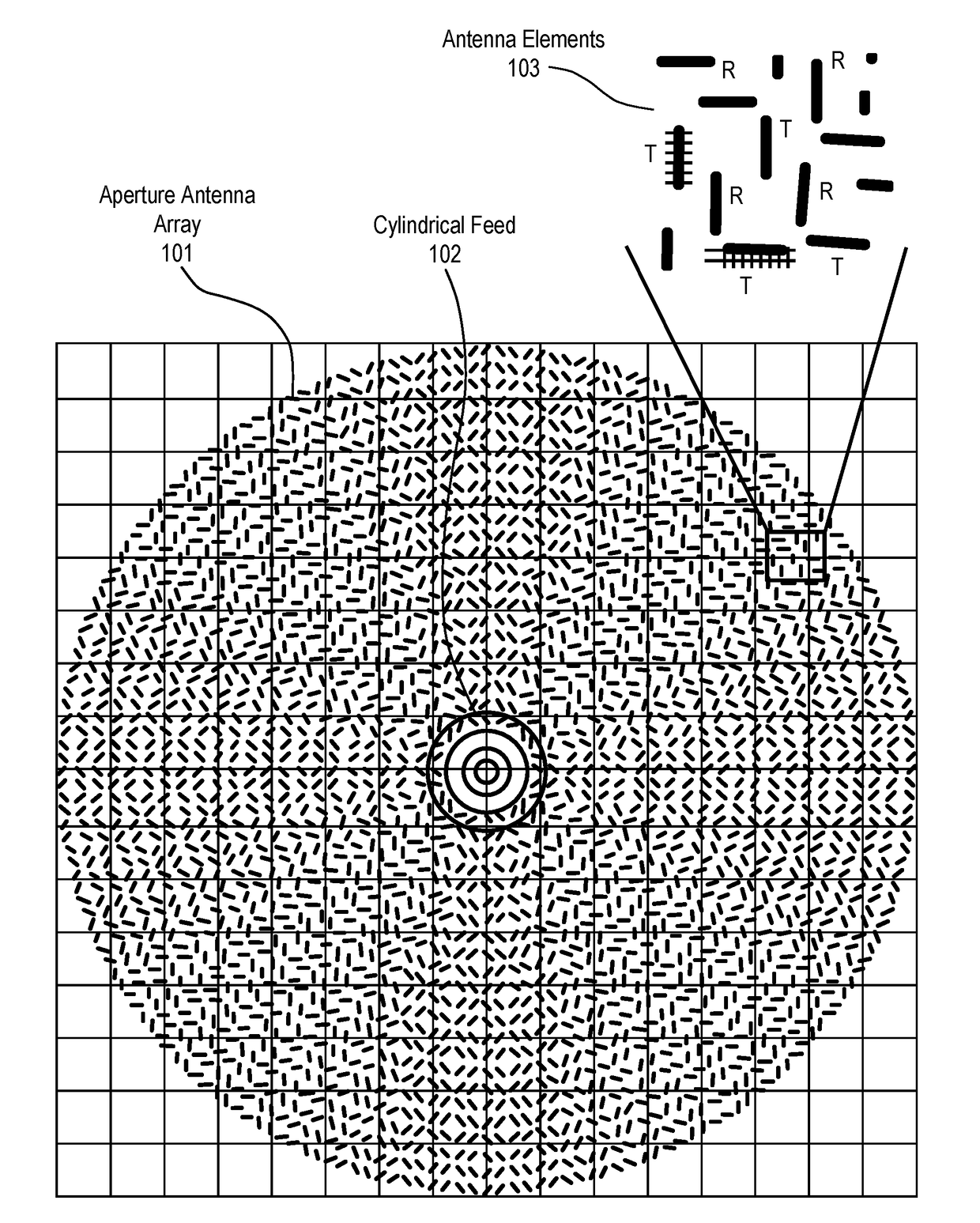
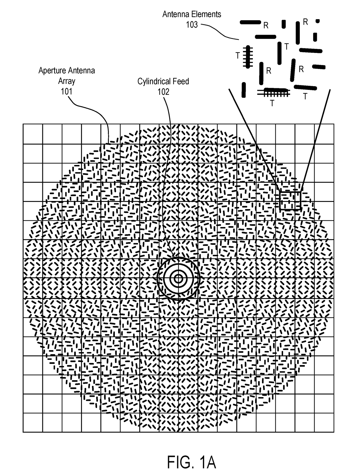
[0078]The techniques described above may be used with flat panel antennas. Embodiments of such flat panel antennas are disclosed. The flat panel antennas include one or more arrays of antenna elements on an antenna aperture. In one embodiment, the antenna elements comprise liquid crystal cells. In one embodiment, the flat panel antenna is a cylindrically fed antenna that includes matrix drive circuitry to uniquely address and drive each of the antenna elements that are not placed in rows and columns. In one embodiment, the elements are placed in rings.

[0079]In one embodiment, the antenna aperture having the one or more arrays of antenna elements is comprised of multiple segments coupled together. When coupled together, the combination of the segments form closed concentric rings of antenna elements. In one embodiment, the concentric rings are concentric with respect to the antenna feed.


PUM


Abstract

A method and apparatus for impedance matching for an antenna aperture are described. In one embodiment, the antenna comprises an antenna aperture having at least one array of antenna elements operable to radiate radio frequency (RF) energy and an integrated composite stack structure coupled to the antenna aperture. The integrated composite stack structure includes a wide angle impedance matching network to provide impedance matching between the antenna aperture and free space and also puts dipole loading on antenna elements.

Description

PRIORITY[0001]The present patent application claims priority to and incorporates by reference the corresponding provisional patent application Ser. No. 62 / 394,582, titled, “WAIM RADOME,” filed on Sep. 14, 2016, provisional patent application Ser. No. 62 / 394,587, titled, “DIPOLE SUPERSTRATE,” filed on Sep. 14, 2016, and provisional patent application Ser. No. 62 / 413,909, titled, LIQUID CRYSTAL (LC)-BASED TUNABLE IMPEDANCE MATCH LAYER,” filed on Oct. 27, 2016.FIELD OF THE INVENTION[0002]Embodiments of the present invention relate to the field of satellite communications; more particularly, embodiments of the present invention relate to wide angle impedance matching structures used in a satellite antenna to increase gain.BACKGROUND OF THE INVENTION[0003]Antenna gain is one of the most important parameters for satellite communications systems since it determines the network coverage and speed. More specifically, more gain means better coverage and higher speed which is critical in the c...

Claims


Application Information

Patent Timeline
IPC IPC(8): H01Q5/335H01Q5/48
CPCH01Q5/335H01Q5/48H01Q15/0066H01Q3/26H01Q9/0442H01Q9/0457H01Q15/0026H01Q21/0031H01Q21/0012H01Q3/44H01Q1/2225H01Q1/38H01Q9/0407H01Q9/285H01Q13/103H01Q21/0056H01Q21/065
Inventor MEHDIPOUR, AIDINSAZEGAR, MOHSENGUENTERBERG, ANTHONYHOWER, ROBERT THOMASEYLANDER, CHRISKOMANDURI, VARADA RAJANSTEVENSON, RYANKUNDTZ, NATHAN
Owner KYMETA
Why Eureka
Try Eureka