Alignment apparatus

a technology of aligning apparatus and aligning parts, which is applied in the field of aligning apparatus, can solve the problems of complex alignment of prosthetic components, patient pain and many other potential complications, and the most difficult steps in total hip replacement surgery, and achieve the effect of improving

Inactive Publication Date: 2018-03-22
INLINE ORTHOPAEDICS
View PDF1 Cites 10 Cited by
  • Summary
  • Abstract
  • Description
  • Claims
  • Application Information

AI Technical Summary

Benefits of technology

[0077]The orientation sensor mount may include one or more of a shock absorber (especially for absorbing shocks associated with driving a prosthetic component into the required position), a clamp for clamping the orientation sensor mount to the surgical device, and a spacer for spacing the orientation sensor from the clamp. The clamp may include a fastener. An advantage of using a spacer is that when the system is used, the orientation sensor may be offset and be less likely to obscure a surgeon's line of sight down the central axis of the surgical device. In one embodiment, the orientation sensor sensing portion is offset from the longitudinal axis of the surgical device.
[0078]Any suitable shock absorber may be used, and the shock absorber may absorb shocks in one, two or more directions, especially in one or two directions. The shock absorber may, for example, comprise a biasing member (such as a spring), and / or comprise pneumatic absorption (for example, like a piston). Similarly, any suitable fastener may be used, including bolts and lock nuts. It may not be necessary for the orientation sensor to include a shock absorber when the orientation sensor is attached to an acetabular reamer, as the effect of the acceleration of the acetabular reamer on the orientation sensor may be effectively ameliorated electronically.

Problems solved by technology

Misalignment of the prosthetic component can result in patient pain and many other potential complications.
Correct alignment of a prosthetic component can be complex, involving multiple steps.
One of the most difficult steps in total hip replacement surgery is correctly aligning the acetabular cup in the acetabulum.
Consequently, it was concluded that “there is overwhelming evidence to show that surgeons cannot consistently position the acetabular components precisely.
Without exception, studies show wide variations in the angles of inclination of the acetabular component and, to an even greater extent, its anteversion.” This is significant as an error in acetabular cup placement of as little as 5° can result in patient complications.
In total hip replacement surgery misalignment of the acetabular cup on the pelvis can result in dislocation of the hip joint, misalignment of the patient's leg, incorrect leg length, decreased joint motion and joint pain.
The long term effects of a misaligned acetabular cup can include accelerated wear of the components, aseptic loosening of the components and potentially early revision surgery.
Furthermore, misalignment may increase the leaching of the prosthesis metal components (for example into the blood stream), which can lead to immune system problems.
However, these landmarks may be obscured during surgery, making it very difficult for a surgeon to assess the optimal orientation.
However, a problem with this approach is that it takes time during an operation to sense the orientation of the acetabular rim, and it is better for elderly patients in particular (for whom hip replacement operations are more common) to be under anaesthetic for shorter periods of time.
Furthermore, there may be natural variations in the surface of the acetabular rim which may introduce errors.
However, a difficulty with this approach is that the size, shape and contour of pelvises vary between patients and consequently it can be difficult to accurately sense the orientation of the pelvis as a whole.

Method used


Image

  • Alignment apparatus
  • Alignment apparatus
  • Alignment apparatus

Examples


Embodiment Construction

[0120]Embodiments and features of the present invention are illustrated with reference to FIGS. 1 to 14. In the figures, like numbers refer to like features.

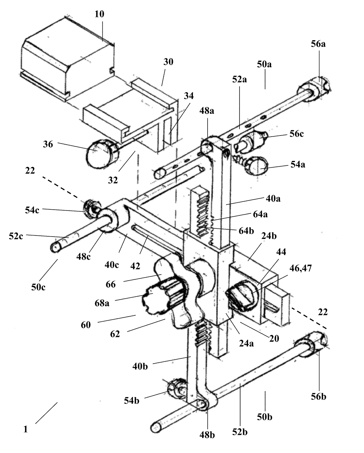
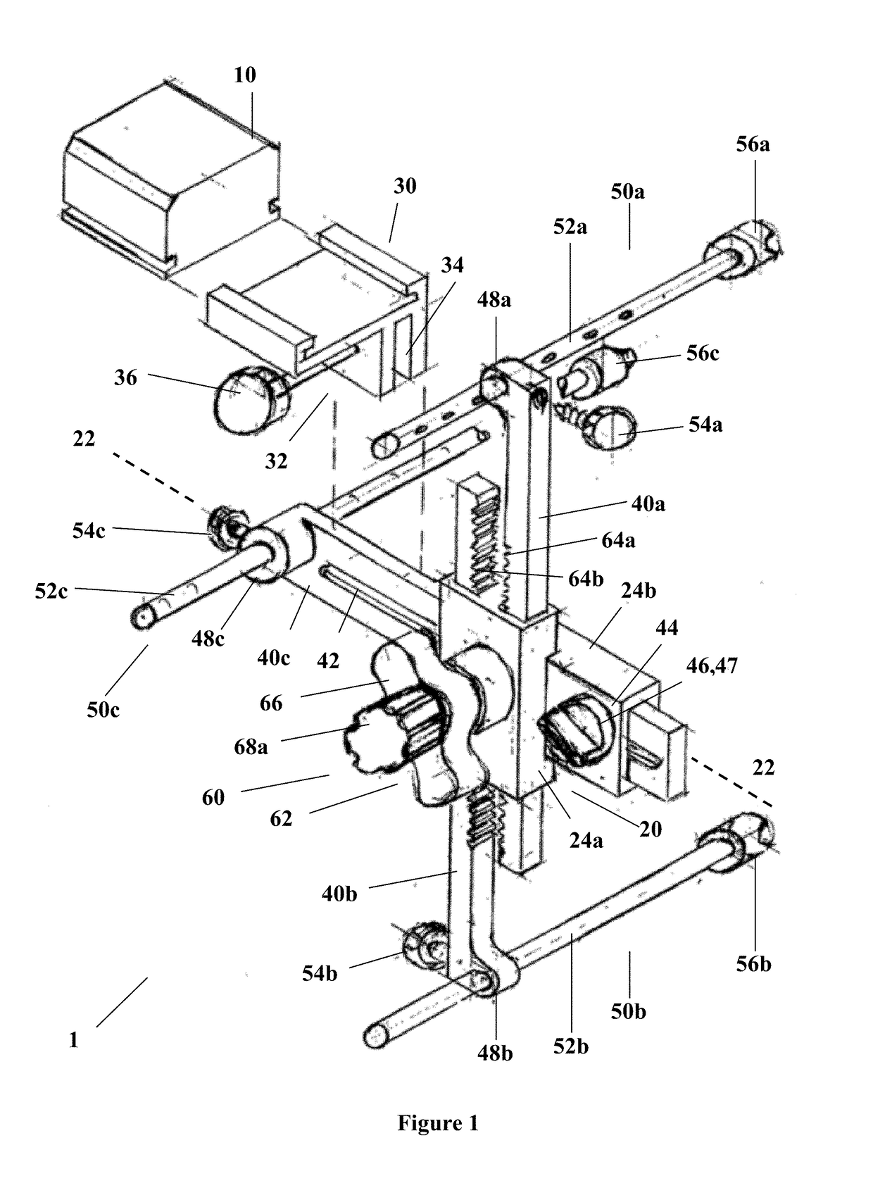
[0121]FIG. 1 illustrates an apparatus 1 for aligning a sensor 10 relative to at least two anatomical reference points of a patient's anatomy. The apparatus 1 includes a body 20 having a central axis 22, a sensor mount 30, and at least two arms 40 extending from the body 20, wherein two of said at least two arms (40a, 40b) are simultaneously and equidistantly moveable relative to the central axis 22. The apparatus 1 also includes at least two aligners 50 connected to the at least two arms 40 for aligning with said at least two anatomical reference points.

[0122]The apparatus 1 includes an arm mechanism 60 for simultaneously and equidistantly moving the arms 40a, 40b relative to the central axis 22. The arm mechanism 60 operates manually and is geared. The arm mechanism 60 is a rack and pinion mechanism. Therefore, the arm mechanis...


PUM


Abstract

The present invention relates to an apparatus for aligning a sensor relative to at least two anatomical reference points of a patient's anatomy. In one embodiment, the apparatus includes: a body having a central axis; a sensor mount positioned relative to the body; at least two arms extending from the body, wherein two of said at least two arms are simultaneously and equidistantly moveable relative to the central axis; and at least two aligners connected to the at least two arms for aligning with said at least two anatomical reference points. The apparatus may also include an apparatus sensor. The present invention also relates to a surgical system for monitoring the orientation of a patient's anatomy, which includes the apparatus. Furthermore, the present invention also relates to a surgical system for guiding a surgical device to an optimal orientation relative to a patient's anatomy, wherein the surgical system includes the apparatus. The present invention also relates to: a method of aligning a sensor relative to at least two anatomical reference points of a patient's anatomy, and to a method of guiding a surgical device to an optimal orientation relative to a patient's anatomy. In one embodiment, the patient's anatomy is the pelvis.

Description

TECHNICAL FIELD[0001]The present invention relates to an alignment apparatus for aligning a sensor relative to at least two anatomical reference points of a patient's anatomy, to surgical systems including the apparatus, and to methods of sensing the orientation of a patient's anatomy and of guiding a surgical device to an optimal orientation involving the apparatus.BACKGROUND ART[0002]It will be clearly understood that, if a prior art publication is referred to herein, this reference does not constitute an admission that the publication forms part of the common general knowledge in the art in Australia or in any other country.[0003]Correct alignment of a prosthetic component is very important in orthopaedic procedures, such as total hip replacement surgery. Optimal alignment may enhance the initial function and long term operability of the prosthetic component. Misalignment of the prosthetic component can result in patient pain and many other potential complications.[0004]Correct a...

Claims


Application Information

Patent Timeline
Patent Type & Authority Applications(United States)
IPC IPC(8): A61B17/17A61B34/20A61B90/00A61B34/00A61F2/46
CPCA61B17/1746A61B34/20A61B90/37A61B34/25A61F2/4657A61B2017/00734A61B2034/2048A61F5/11A61B2090/372A61F2/4603
Inventor FRY, DONCOOPER, DAVID JOHNWADLEY, DAVID JOHNFORD, MARTIN JOHN
Owner INLINE ORTHOPAEDICS
Why Eureka
Try Eureka