Donor panel antenna

a panel antenna and antenna technology, applied in the field of directive antennas, can solve the problems of increasing the noise level in the receiver, poor front to back ratio, and the antenna does not possess satisfactory directional gain, so as to reduce pim and interference, increase the wind load, and reduce the effect of side lobe gain

Inactive Publication Date: 2018-03-22
WESTELL
View PDF3 Cites 13 Cited by
  • Summary
  • Abstract
  • Description
  • Claims
  • Application Information

AI Technical Summary

Benefits of technology

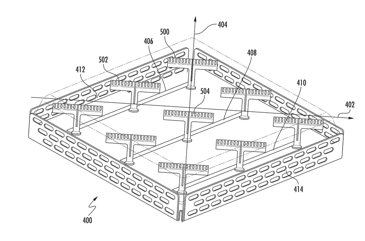
[0008]Embodiments of the invention have certain advantages. By providing a u-shaped, rigid support structure under the antenna radome, antennas according to certain embodiments can withstand increased wind loads compared to conventional designs. Additionally, by providing a steel, symmetrical support structure under the antenna reflector, which is mechanically coupled to a mounting bracket, and then to a mast, antennas according to embodiments of the invention can be more securely mounted during installation as compared with conventional designs incorporating aluminum mounting hardware. Embodiments of the invention use printed circuit board (“PCB”) connections from the antenna feed line to each individual dipole antenna element. This eliminates the need for cables and cable connectors, which provides reduced PIM and interference, particularly when the antenna is subject to mechanical shock. The use of an array of dipole radiators, arranged at a diagonal with respect the reflector walls, provides for less side lobe gain, a higher F / B ratio, and more forward gain, i.e., better directionality and lower interference. In particular, embodiments of the invention provide a minimal spacing between edge dipole elements and the interior walls of the reflector, which reduces fringing effects and leaking of energy into side lobes. Additional advantages will be evident to the person of ordinary skill in the art in view of the following detailed description.

Problems solved by technology

However, existing configurations of the conventional panel antenna tend to have excessive side lobe radiation, which may cause electromagnetic interference, and which is wasteful from an energy efficiency standpoint.
For example, in receiving antennas, side lobes may pick up interfering signals and increase the noise level in the receiver.
Further, many conventional panel antennas do not possess satisfactory directional gain (i.e., have a poor front to back ratio) and often suffer from strong wind load due to their physical configuration.
This makes certain conventional antennas unsuitable for use in high-wind environments, such as areas prone to hurricanes and tornados.
Additionally, the materials used in the fabrication of conventional panel antenna tend to result in higher than optimal manufacturing costs.

Method used


Image

  • Donor panel antenna
  • Donor panel antenna
  • Donor panel antenna

Examples


Embodiment Construction

[0032]References throughout this specification to “one embodiment,”“an embodiment,”“a related embodiment,” or similar language mean that a particular feature, structure, or characteristic described in connection with the referred to “embodiment” is included in at least one embodiment of the present invention. Thus, appearances of the phrases “in one embodiment,”“in an embodiment,” and similar language throughout this specification may, but do not necessarily, all refer to the same embodiment. It is to be understood that no portion of disclosure, taken on its own and in possible connection with a figure, is intended to provide a complete description of all features of the invention.

[0033]In addition, the following disclosure may describe features of the invention with reference to corresponding drawings, in which like numbers represent the same or similar elements wherever possible. In the drawings, the depicted structural elements are generally not to scale, and certain components a...


PUM


Abstract

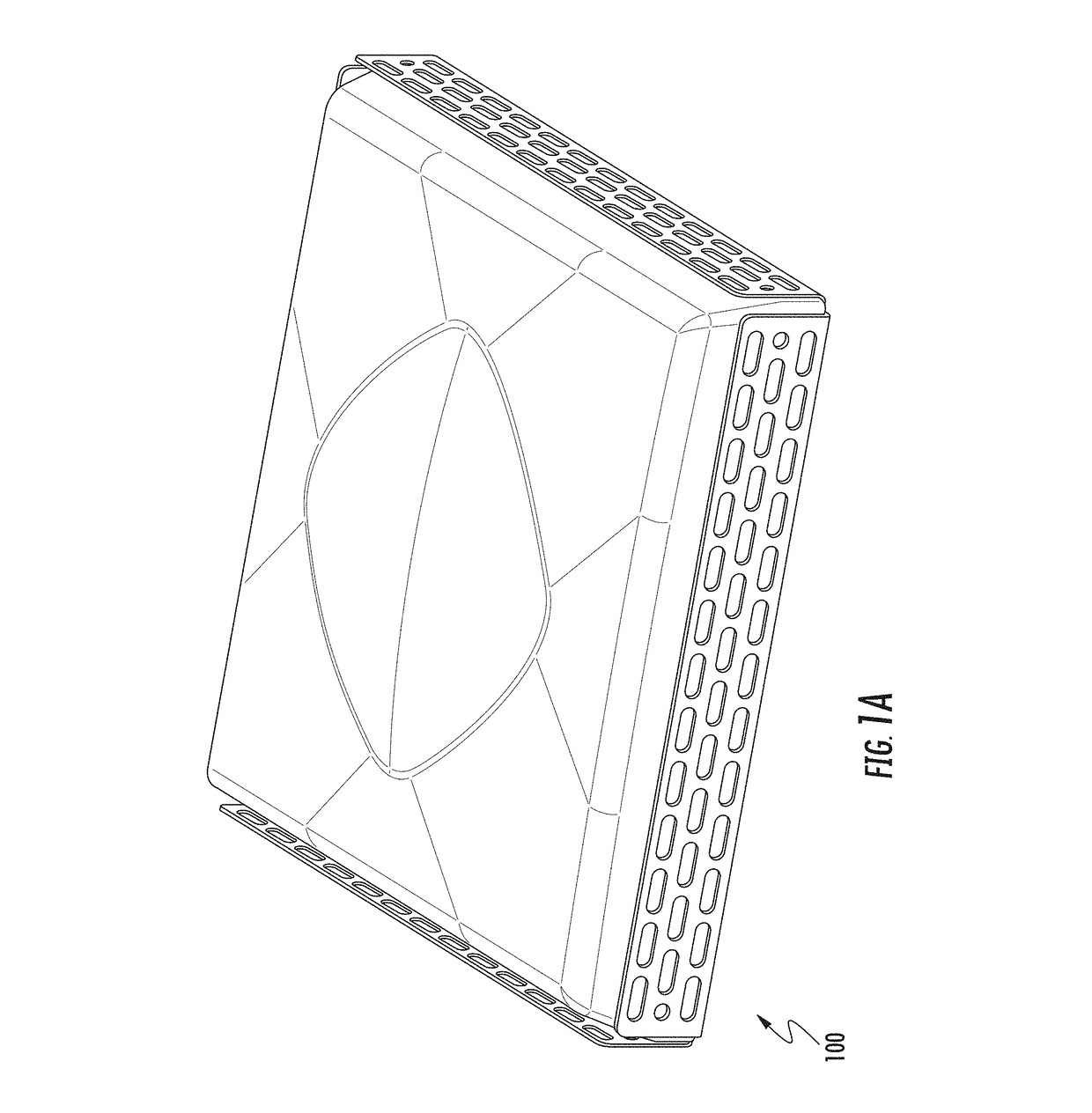
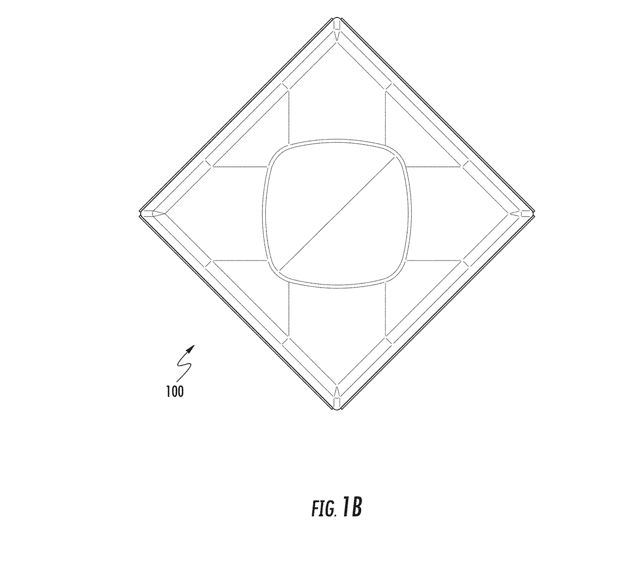
A low band panel antenna is described. The panel antenna has a double bend reflector, a N×M array of dipole elements symmetrically disposed within an interior portion of the double bend reflector, a five-sided cover. Further, a top portion of the five-sided cover has a dome that is disposed substantially in the middle of the top portion. Moreover, the band panel can be mounted by using a mounting assembly, which further contains two brackets and a concave brace.

Description

CROSS REFERENCE TO RELATED APPLICATIONS[0001]This Application claims priority to U.S. Provisional Patent Application 62 / 396,061, filed on Sep. 16, 2016, the disclosure of which is incorporated herein in its entirety.TECHNICAL FIELD[0002]The present invention relates to a directive antenna and, more particularly, to a vertically polarized, physically compact panel antenna for use in wireless data communication.BACKGROUND OF THE INVENTION[0003]Conventional panel antennas are available in a number of different configurations and materials. However, existing configurations of the conventional panel antenna tend to have excessive side lobe radiation, which may cause electromagnetic interference, and which is wasteful from an energy efficiency standpoint. For example, in receiving antennas, side lobes may pick up interfering signals and increase the noise level in the receiver. Further, many conventional panel antennas do not possess satisfactory directional gain (i.e., have a poor front ...

Claims


Application Information

Patent Timeline
Patent Type & Authority Applications(United States)
IPC IPC(8): H01Q21/06H01Q1/42H01Q21/00H01Q15/14H01Q1/00
CPCH01Q21/062H01Q1/42H01Q21/0031H01Q15/14H01Q1/005H01Q1/246H01Q19/10
Inventor TEILLET, ANTHONYSUNDARARAJAN, NIRANJANBUCH, YATIN
Owner WESTELL
Why Eureka
Try Eureka