Umbrella-shaped building structure
A building structure and umbrella-shaped technology, which is applied in the direction of building components, special structures, building structures, etc., can solve the problems of large cross-sectional dimensions of beams and columns, and achieve the effects of improving earthquake resistance, increasing rainproof and sunshade functions, and simple appearance effects
- Summary
- Abstract
- Description
- Claims
- Application Information
AI Technical Summary
Problems solved by technology
Method used
Image
Examples
Embodiment 1
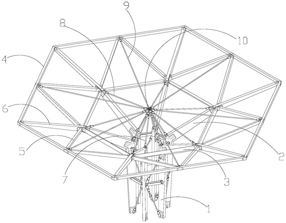
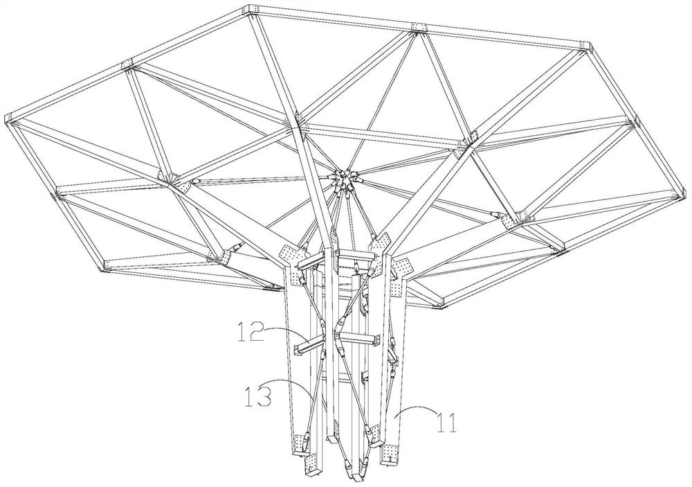
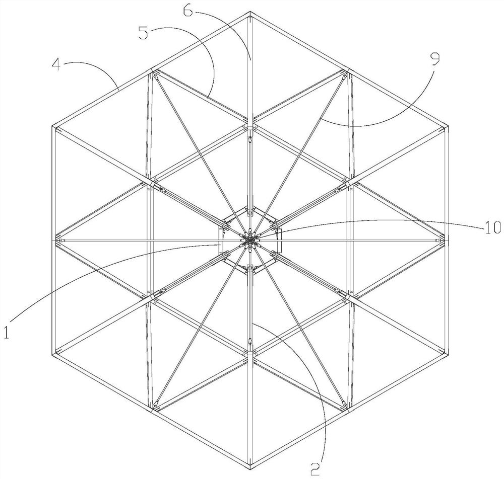
[0036] Such as Figure 1-3 As shown, the present embodiment provides an umbrella-shaped building structure, which includes a support column 1, a first support beam 2, a first beam column 3, a second beam column 4, a second support beam 6, a A pull rod 7, a second pull rod 8, a drag cable 9, a central connector 10 and a membrane coating; Beam column 4, second support beam 6, first pull rod 7, second pull rod 8, stay cable 9 and the top surface of central connector 10, described first support beam 2 is N, and the bottom end is equally spaced with support The outer periphery of the top of the column 1 is connected, and the first beam column 3 is N pieces connected end to end to form a first beam column frame, and the first beam column frame is arranged at intervals on the outer side above the first support beam 2 and the first The top of the support beam 2 is connected to the joint of the adjacent first beam column 3; the second beam column 4 is N and connected end to end to for...
Embodiment 2
[0039] Such as Figure 1-3 As shown, the umbrella-shaped building structure further includes 2N third beam columns 5 , and the third beam columns 5 connect the middle part of the second beam column 4 and the junction of the adjacent first beam columns 3 . The stability of the connection between the first beam column 3 and the second beam column 4 can be improved by arranging the third beam 5 .
Embodiment 3
[0041] Such as figure 2 As shown, the support column 1 includes a column body 11, a third pull rod 12 and a crossbeam 13. There are multiple columns 11, and a plurality of (preferably two) adjacent columns 11 are arranged horizontally and up and down The spaced beams 13 are connected, and the third tie rod 12 is obliquely connected to the ends of the adjacent beams 13 or the bottom of the column 11 . By arranging the third tie rod 12 and the beam 13, the firmness of the connection of the column 11 can be improved, and the overall stability can be improved.
PUM
 Abstract
Description
Claims
Application Information
 - R&D
- Intellectual Property
- Life Sciences
- Materials
- Tech Scout
- Unparalleled Data Quality
- Higher Quality Content
- 60% Fewer Hallucinations
Browse by: Latest US Patents, China's latest patents, Technical Efficacy Thesaurus, Application Domain, Technology Topic, Popular Technical Reports.
© 2025 PatSnap. All rights reserved.Legal|Privacy policy|Modern Slavery Act Transparency Statement|Sitemap|About US| Contact US: help@patsnap.com


