
Ultraviolet light module having output power control mechanism

Active Publication Date: 2018-03-22
BOLB
View PDF18 Cites 13 Cited by
  • Summary
  • Abstract
  • Description
  • Claims
  • Application Information

AI Technical Summary

Benefits of technology

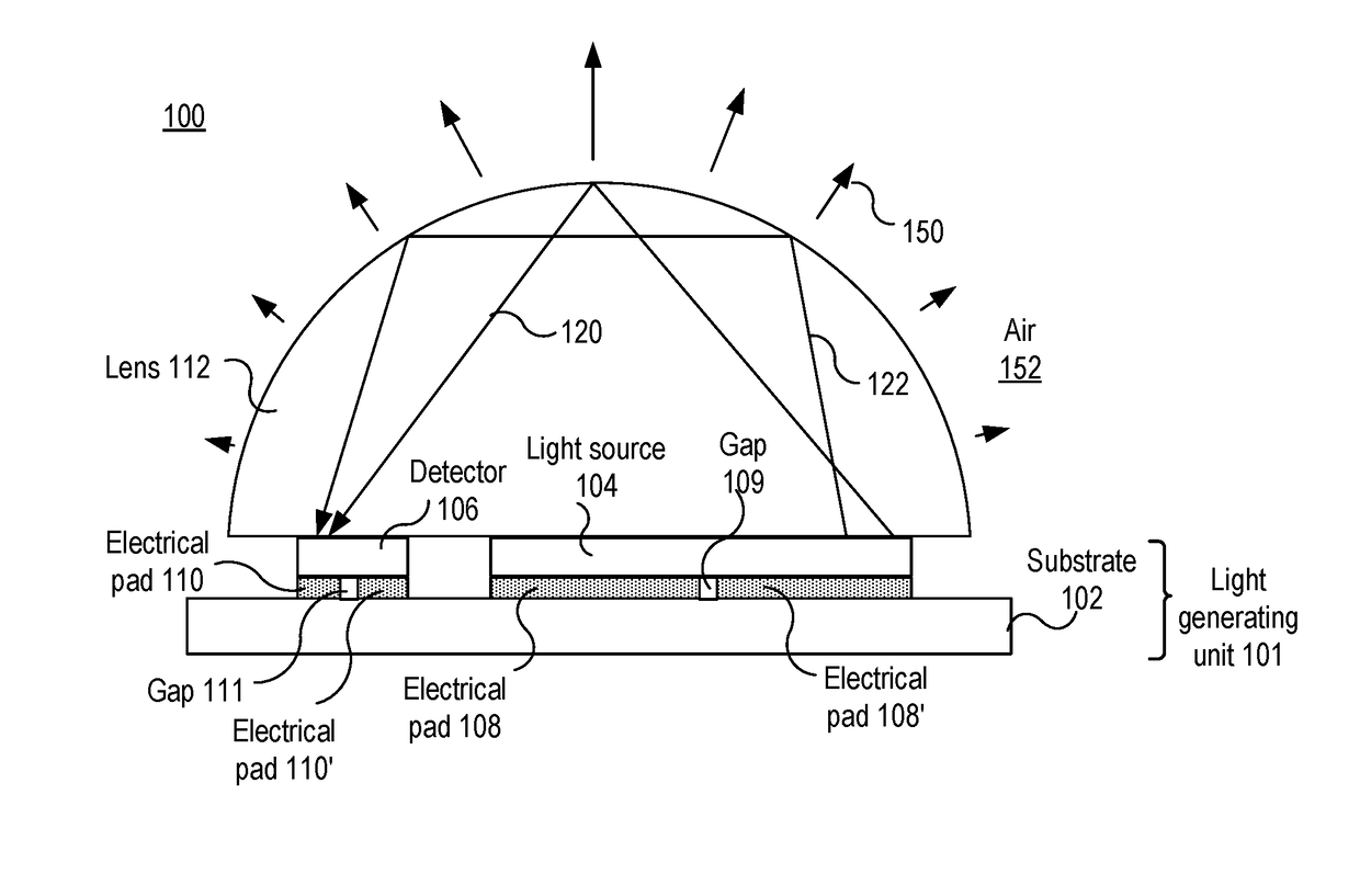
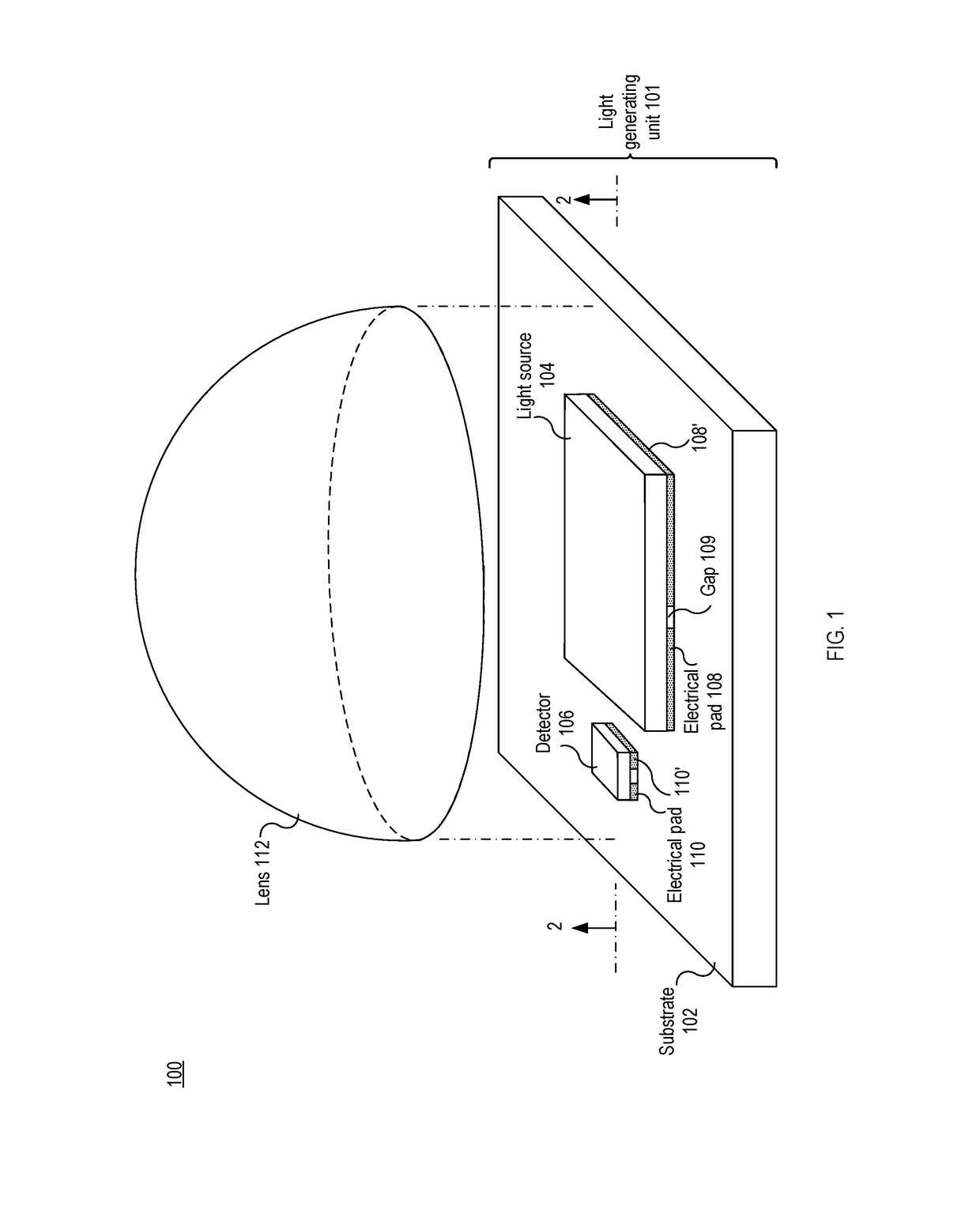
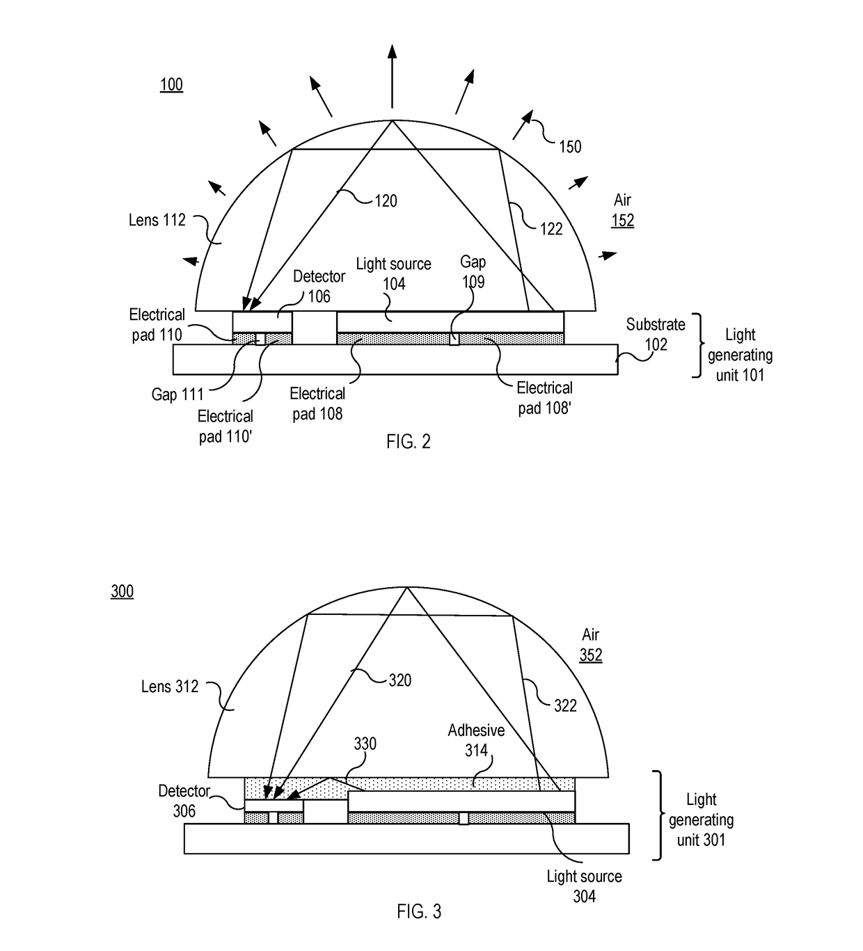
This patent describes an apparatus for generating light. The apparatus includes a substrate, a light source, a detector, and a lens or a waveguide. The light source generates output light, which is then directed to the detector by the lens or the waveguide. The lens or waveguide allows a portion of the output light to be reflected and directed back to the detector, resulting in a measurable photocurrent that can be used to control the light source's output power. The technical effect is an efficient and precise control over the output power of a light source through a lens or waveguide.

Problems solved by technology

In general, controlling a UV light source is difficult since human cannot directly perceive the UV light.
Since human cannot directly perceive the UV light, visual inspection of the output light cannot determine whether the UV light source is properly working or not.
However, the conventional feedback mechanisms have a few problems.
Second, the intensity of the light emitted by a conventional UV light source is very low.
In addition, the UV light is absorbed by the air, causing the intensity of light incident on a UV detector to decrease rapidly as the optical path length between the UV light source and detector increases.

Method used


Image

  • Ultraviolet light module having output power control mechanism
  • Ultraviolet light module having output power control mechanism
  • Ultraviolet light module having output power control mechanism

Examples


Embodiment Construction

[0018]In the following description, for the purposes of explanation, specific details are set forth in order to provide an understanding of the invention. It will be apparent, however, to one skilled in the art that the invention can be practiced without these details. One skilled in the art will recognize that embodiments of the present invention, described below, may be performed in a variety of ways and using a variety of means. Those skilled in the art will also recognize additional modifications, applications, and embodiments are within the scope thereof, as are additional fields in which the invention may provide utility. Accordingly, the embodiments described below are illustrative of specific embodiments of the invention and are meant to avoid obscuring the invention.

[0019]A reference in the specification to “one embodiment” or “an embodiment” means that a particular feature, structure, characteristic, or function described in connection with the embodiment is included in at...


PUM


Abstract

The invention relates to UV light modules that generate UV light. The UV light module includes: a substrate; a light source mounted on a top surface of the substrate, the light source generates output light; a detector mounted on the top surface of the substrate, the detector detects light incident thereon; and a lens disposed over the light source and the detector. The lens includes a surface on which a portion of the output light is internally reflected and the portion of the output light travels through the lens to the detector.

Description

BACKGROUNDTechnical Field[0001]The present invention relates to lighting devices, and more particularly, to ultraviolet light modules having output power control mechanisms.Background of the Invention[0002]UV light sources, such as UV light emitting diodes (LEDs), have been used in various applications, such as industrial and cosmetic curing, sterilization of harmful bacteria, indoor gardening, and treatment of human skin condition, so on. For example, AIGaN LEDs emitting at wavelengths in the range of 240-365 nm can be used as ultraviolet light panel backlight sources for germicidal and medical applications. In this case, the input power to the light source must be controlled so that the intensity of the light from the light source is maintained at the target level to ensure sterilization of the germs.[0003]In general, controlling a UV light source is difficult since human cannot directly perceive the UV light. The lens of the human eye blocks most of the light in the wavelength ra...

Claims


Application Information

Patent Timeline
IPC IPC(8): H05B33/08G01J1/42F21V23/04F21V5/04F21V7/00H05B44/00
CPCH05B33/0851G01J1/429G01J2001/4247F21V5/04F21V7/00F21V23/0457A01G7/045A61N5/00A61N5/06A61N5/0616A61N2005/0651A61N2005/0661H05B45/12A01G9/249A61B2018/00452Y02P60/14
Inventor ZHANG, JIANPINGZHOU, LINGGAO, YING
Owner BOLB
Features
  • Generate Ideas
  • Intellectual Property
  • Life Sciences
  • Materials
  • Tech Scout
  • Unparalleled Data Quality
  • Higher Quality Content
  • 60% Fewer Hallucinations
Learn More