
Soil sensor grid

a sensor grid and soil technology, applied in the field of soil sensor grids, can solve the problems of increasing water cost, increasing water consumption, and wasting a large amount of water, and achieve the effects of optimizing water usage, optimal water usage, and maintaining the landscap

Active Publication Date: 2018-03-29
SMART RAIN SYST
View PDF6 Cites 5 Cited by
  • Summary
  • Abstract
  • Description
  • Claims
  • Application Information

AI Technical Summary

Benefits of technology

The patent describes a system that combines an irrigation system and a soil sensor system to optimize water usage. The system has a controller that receives feedback from the sensors to determine when and how much water is needed. This helps to save water by only using it in areas where it is necessary. The sensor grid can be integrated with the irrigation system or separate and independent, and can communicate with the controller to ensure the optimal amount of water for the landscape.

Problems solved by technology

Water is becoming an increasingly scarce resource.
This increasing scarcity is pressuring consumers and governments alike to consider how they use water and how they can use it more wisely.
The costs of water are also increasing as a result of scarcity, and home owners, farms, businesses and the like are under pressure to reduce costs associated with using water.
Much of that water is wasted due to inefficient irrigation methods and systems.
However, doing so often requires expertise in landscape irrigation and may require expensive equipment.
Furthermore, some water users are unsure whether they will ever recoup the investment they make in the system.
Many water users forgo the benefits of more sophisticated irrigation systems and waste water as a result.
In addition, many irrigation systems can over water or under water because there is no feedback from the soil to know if the grounds are getting enough or too much water.
Distribution of water is consistently one of the biggest problems in the irrigation and sprinkler industry.
However, sadly this information may not be very sight specific or landscape specific for a landscape owner or manager.

Method used


Image

  • Soil sensor grid
  • Soil sensor grid
  • Soil sensor grid

Examples


Embodiment Construction

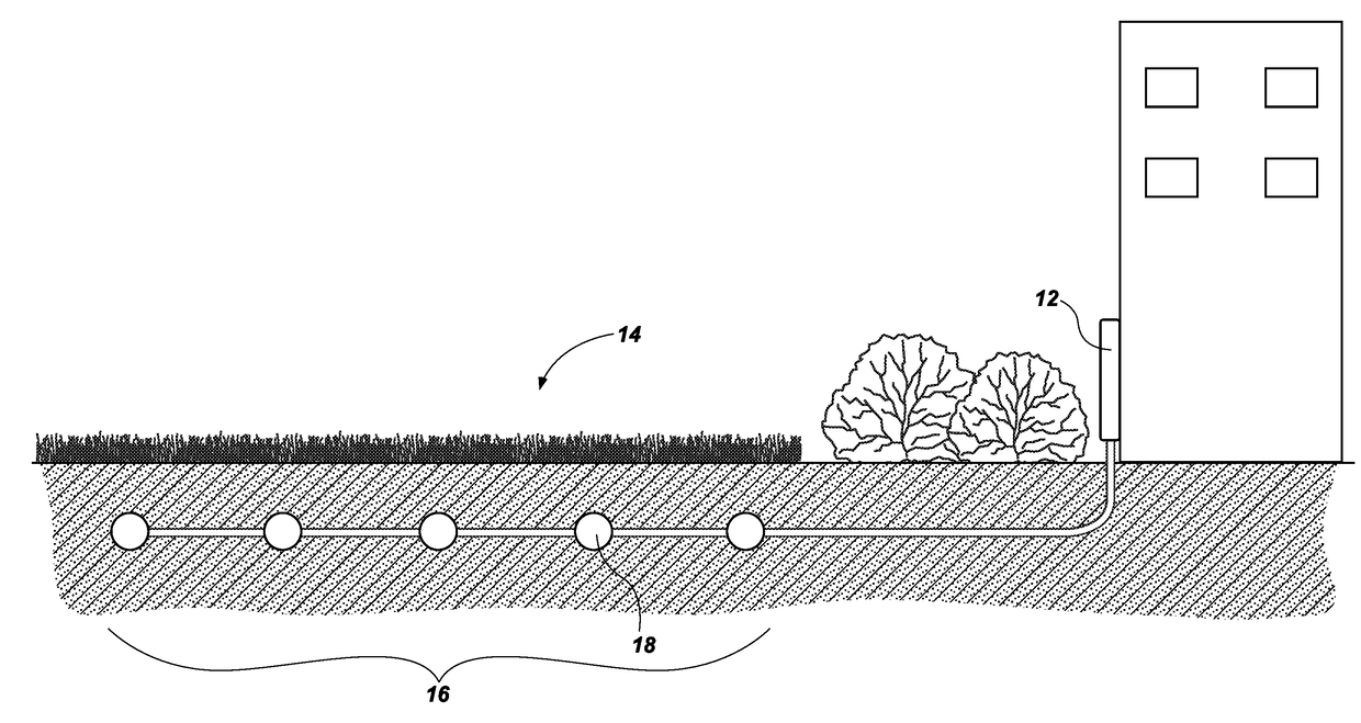
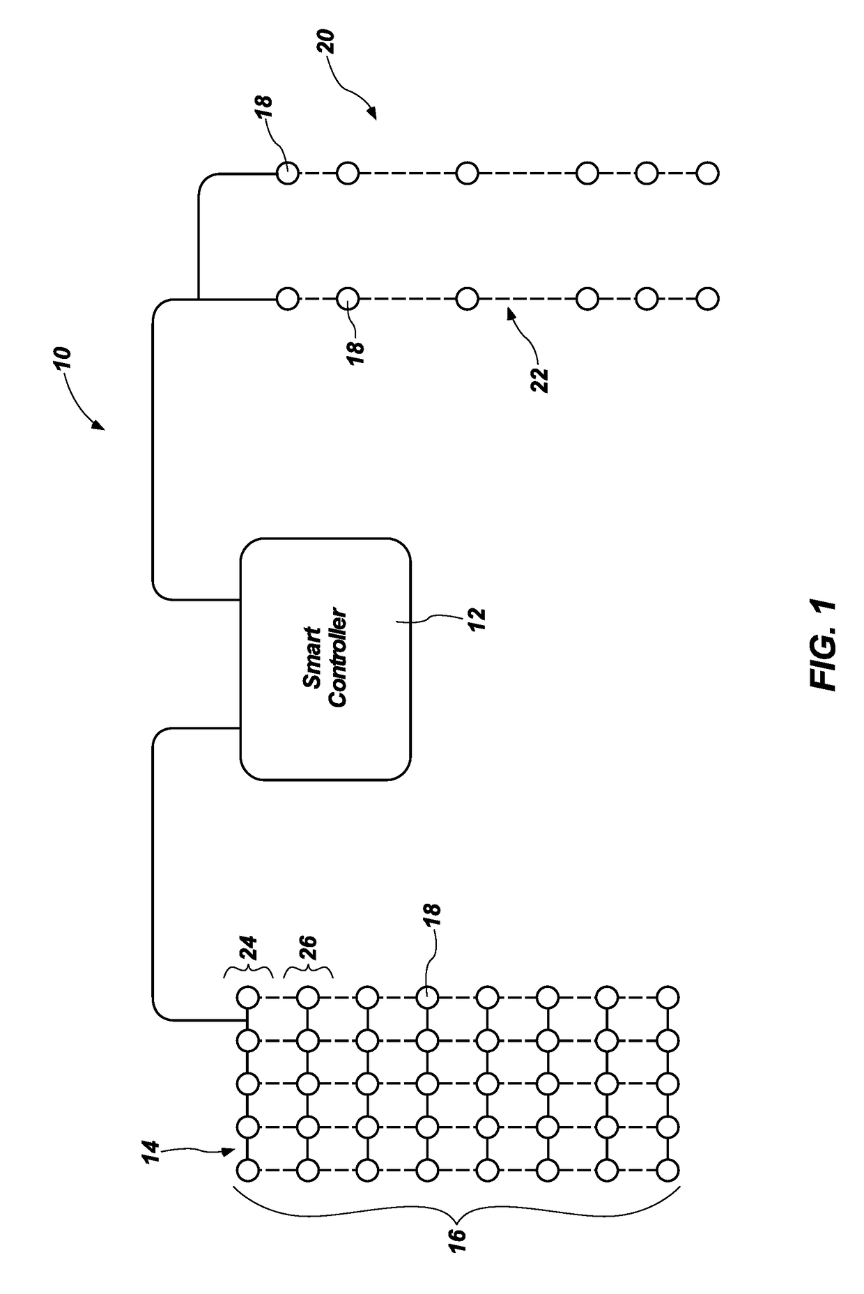
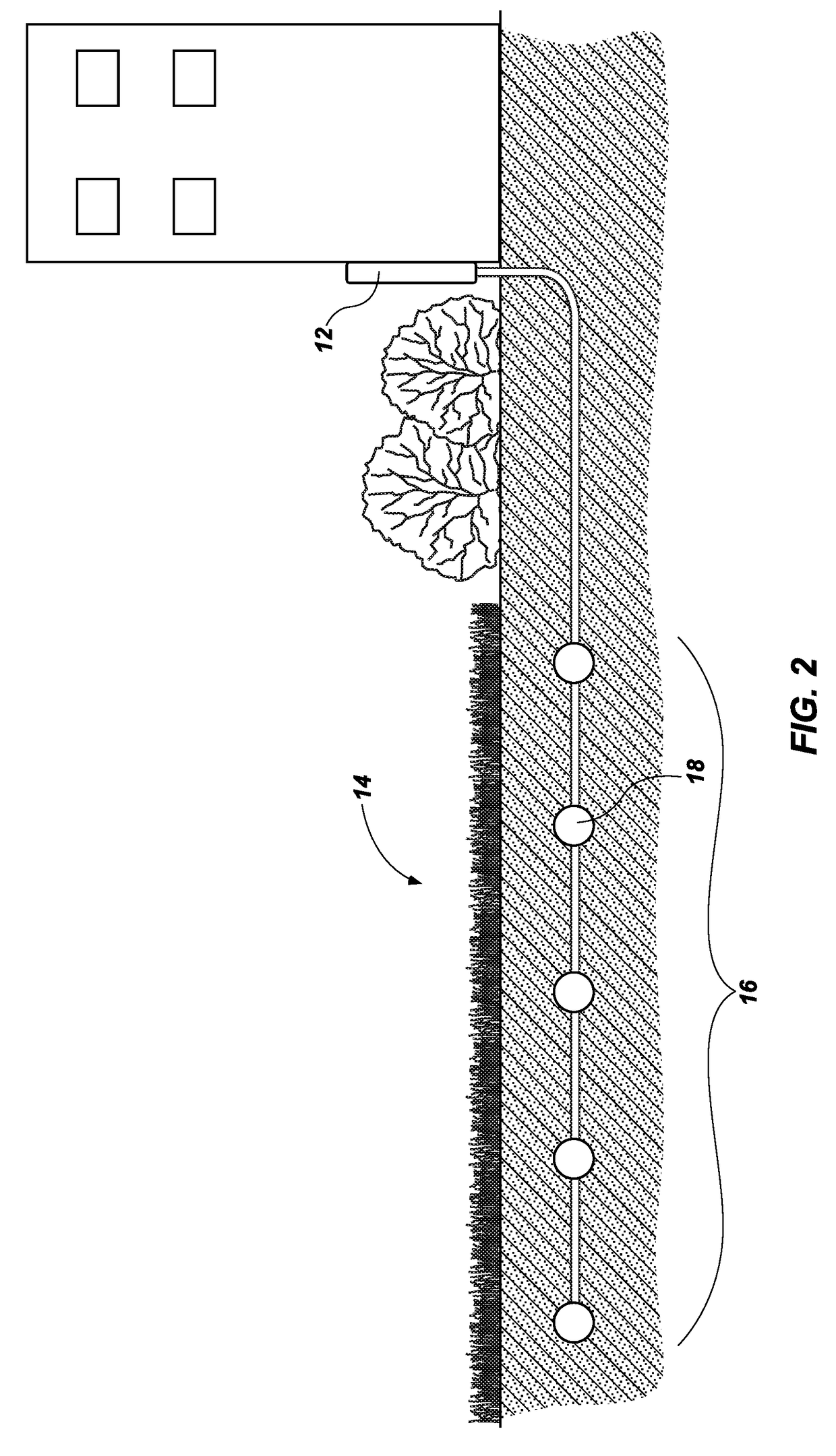
[0017]Referring in general to the accompanying drawings, various embodiments of the present method and system are illustrated to show the structure and methods for a sensor grid which may be integrated with an irrigation system. Common elements of the illustrated embodiments are designated with like numerals. It should be understood that the figures presented are not meant to be illustrative of actual views of any particular portion of the actual device structure, but are merely schematic representations which are employed to more clearly and fully depict embodiments of the system.

[0018]The following provides a more detailed description of ways to implement the present system and method and various representative embodiments thereof. The following description sets forth the proper method of installing and implementing a soil sensor grid system and how the system will interface with a smart controller, or controller, to adequately water specific parts of a property or landscape. In t...


PUM


Abstract

A system and method for providing optimal irrigation or watering, and more specifically providing a soil sensor grid placed in the ground of a landscaped property, in commercial, residential or even agricultural areas. The soil sensor grid can allow for optimal water usage in a specified irrigation area by providing real time data to an irrigation system and a user to optimize water usage. A soil sensor grid, or moisture sensor grid, may be installed on a property, buried in the ground, to provide current and real time feedback of the current moisture levels of the soil. The moisture data is uploaded to the cloud and provided to a user and the irrigation system allowing a user to automatically or manually manipulate the irrigation system to properly water or irrigate different portions of the property based on the data from the soil sensor grid.

Description

TECHNICAL FIELD[0001]This disclosure relates generally to irrigation management, and more specifically to providing a soil sensor grid, placed in the ground of a landscaped property, in commercial, residential or even agricultural areas. The soil sensor grid can allow for optimal water usage in a specified irrigation area.BACKGROUND OF RELATED ART[0002]Water is becoming an increasingly scarce resource. This increasing scarcity is pressuring consumers and governments alike to consider how they use water and how they can use it more wisely. The costs of water are also increasing as a result of scarcity, and home owners, farms, businesses and the like are under pressure to reduce costs associated with using water.[0003]Many irrigation users need water to maintain the grounds of their business facilities, their farms or ranches, and their residences. Some estimates speculate that landscape irrigation accounts for nearly one-third of all residential water use, and totals almost nine bill...

Claims


Application Information

Patent Timeline
IPC IPC(8): A01G25/16G05D7/06G05B19/042B05B12/08
CPCG05B2219/2625A01G25/167B05B12/084G05B19/0428G05D7/0617G05B19/042
Inventor LARSEN, RUDY LARS
Owner SMART RAIN SYST
Learn More