Cooling device and cooling module

Inactive Publication Date: 2018-03-29
DENSO CORP
View PDF4 Cites 7 Cited by
  • Summary
  • Abstract
  • Description
  • Claims
  • Application Information

AI Technical Summary

Benefits of technology

[0016]With this configuration, the quantity of air blown from the first opening of the duct to the rear side of the front engine room relative to the drive engine in the travelling dir

Problems solved by technology

In an automobile having an exhaust manifold arranged rear of a drive engine, however, the cooling device fails to cool the exhaust manifold with air flow.
This makes ventil

Method used


Image

  • Cooling device and cooling module
  • Cooling device and cooling module
  • Cooling device and cooling module

Examples


Example

First Embodiment

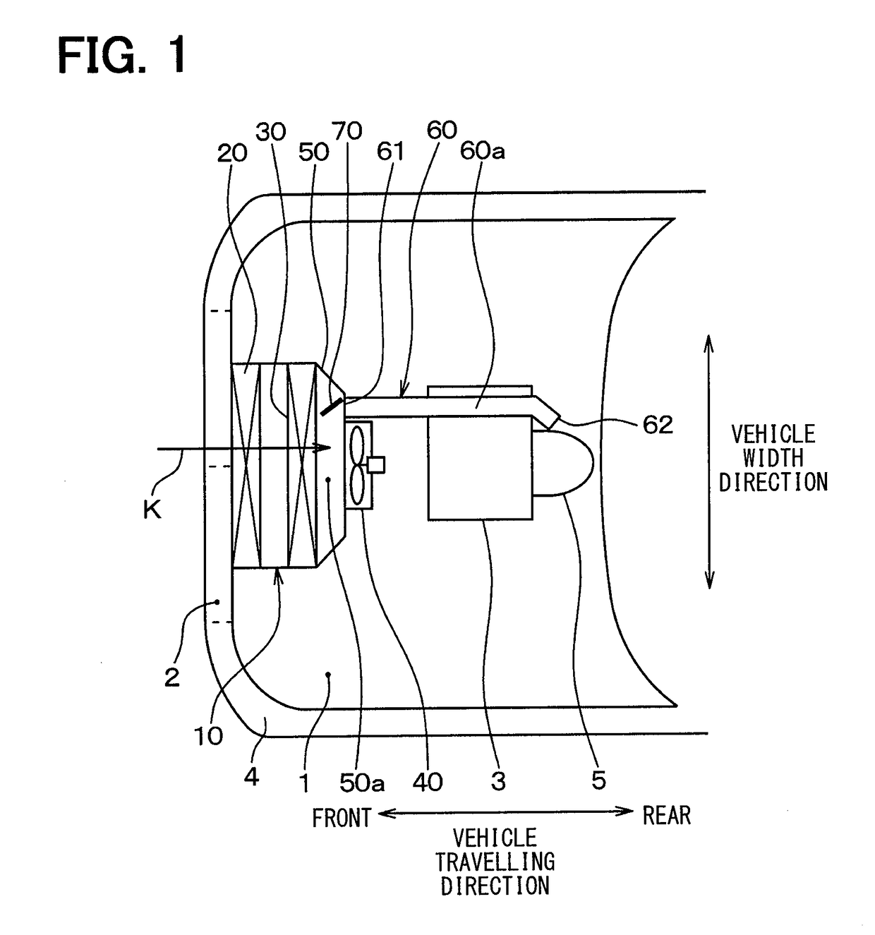
[0044]FIG. 1 illustrates a cooling module 10 according to a first embodiment, for an automobile to which a cooling device of the present disclosure is applied.

[0045]The cooling module 10 according to the present embodiment is arranged between a front grille opening 2 and a drive engine 3 in a front engine room 1 of an automobile. The front grille opening 2 is an opening in a front grille 4 of the automobile, and is opened at a front side of the front grille 4 in a vehicle-travelling direction with respect to the front engine room 1. The front engine room 1 is a space defined front of a passenger compartment of the automobile in the vehicle-travelling direction, the drive engine 3 is arranged in the front engine room 1.

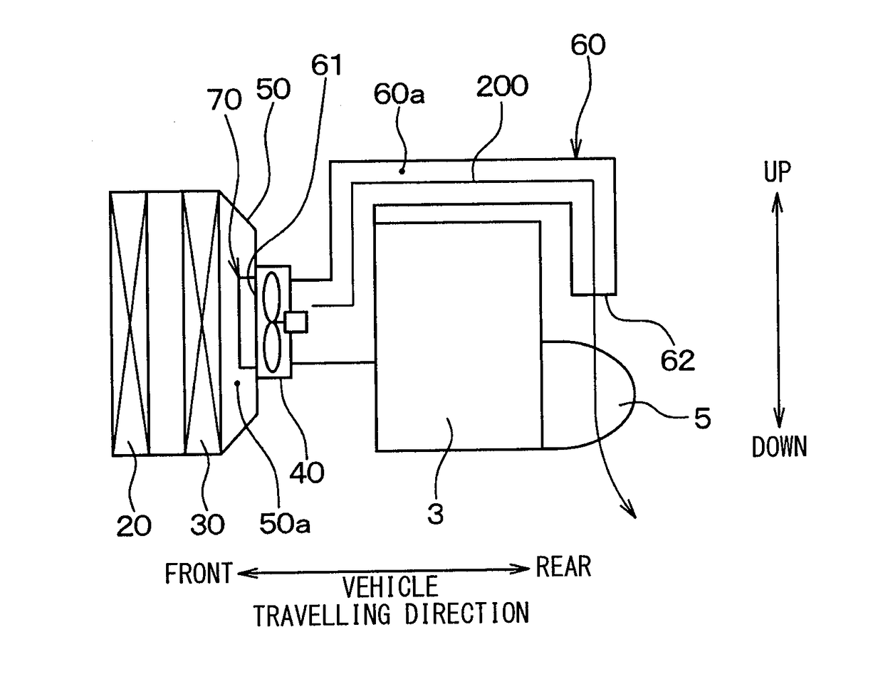
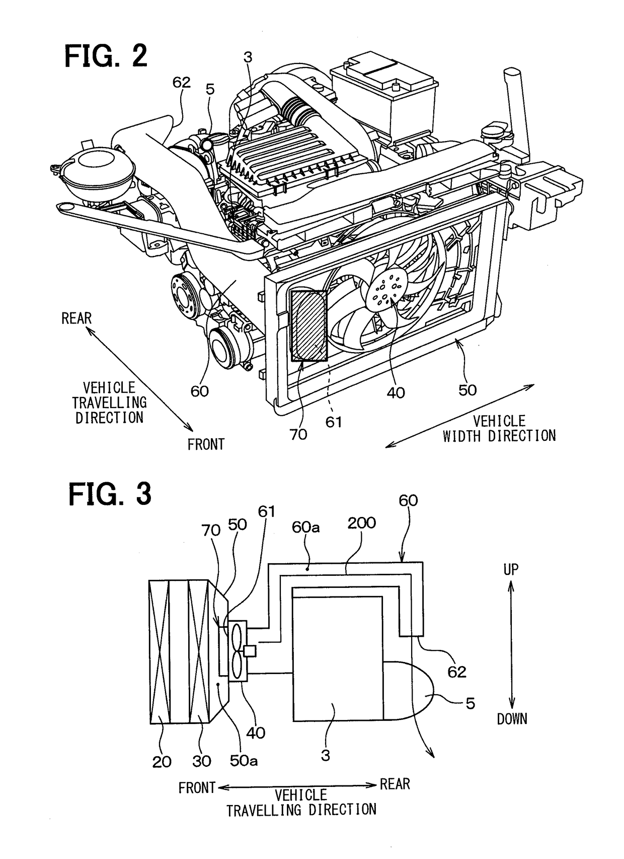
[0046]Specifically, as illustrated in FIG. 1, the cooling module 10 includes a condenser 20, a radiator 30, an electric fan 40, a shroud 50, a duct 60, and a valve 70.

[0047]The condenser 20 is arranged rear of the front grille opening 2 in the vehicle-t...

Example

Second Embodiment

[0106]In the first embodiment, when the speed of the automobile is low, the valve 70 is closed. In a second embodiment, alternatively, when the speed of the automobile is low, the degree of opening of the valve 70 is controlled in accordance with the temperature of the exhaust manifold 5.

[0107]The present embodiment is different from the first embodiment in the cooling control processing of the electronic control unit 90. The cooling control processing in the present embodiment will be described below with reference to FIGS. 8 and 9.

[0108]FIG. 8 is a flowchart of the cooling control processing according to the present embodiment. The flowchart of FIG. 8 is acquired by adding S190, S191 to the flowchart of FIG. 5. The same steps in FIG. 8 as those in FIG. 5 are given the same reference signs, and the description thereof will not be given here. The electronic control unit 90 executes the cooling control processing in accordance with the flowchart of FIG. 8 instead of ...

Example

Third Embodiment

[0116]In a third embodiment, holes 60c, 60d are formed in the duct 60 of the cooling module 10 of the first embodiment to cool components to be cooled other than the exhaust manifold 5.

[0117]FIG. 10 is a side view of the cooling module 10 according to the present embodiment. The cooling module 10 according to the present embodiment is acquired by forming the holes 60c, 60d in the duct 60 of the cooling module 10 of the first embodiment. Thus, the holes 60c, 60d in the duct 60 will be described below, and the description of the other configurations will not be given here. The same components in FIG. 10 as those in FIG. 3 are given the same reference signs.

[0118]The holes 60c, 60d are opened from the air passage 60a to the outside of the duct 60 between the openings 61, 62 of the duct 60. The holes 60c, 60d are located above the components to be cooled (not illustrated) in the vertical direction. Examples of the components to be cooled include an alternator and a waste...


PUM


Abstract

A cooling device for an automobile that includes a front opening opened in a front engine room, a first air blower arranged in the front engine room on a front side of a drive engine, and an introduction passage for guiding, toward the first air blower, air to flow from the front side of the front opening through the front opening is configured to cool the drive engine with the air flow passing from the introduction passage to the drive engine via the first air blower. The cooling device includes a duct having a first opening opened in the introduction passage and a second opening opened to rear of the drive engine in the front engine room, to form an air passage for air to flow between the first opening and the second opening.

Description

CROSS REFERENCE TO RELATED APPLICATIONS[0001]This application is based on Japanese Patent Application No. 2014-249101 filed on Dec. 9, 2014 and Japanese Patent Application No. 2015-76860 filed on Apr. 3, 2015, the disclosures of which are incorporated herein by reference.TECHNICAL FIELD[0002]The present disclosure relates to a cooling device and a cooling module.BACKGROUND ART[0003]A cooling device has been proposed, which is applied to an automobile having an exhaust manifold arranged front of a drive engine in the travelling direction in a front engine room, for cooling the exhaust manifold with air flow (refer to, for example, Patent Literature 1).[0004]The cooling device has a duct formed therein. The duct causes a flow of air, which is introduced from an opening of a front grille and passes through a radiator, to pass around the exhaust manifold, and then guides the flow of air to a region below a rear portion of the drive engine. With this configuration, the exhaust manifold i...

Claims


Application Information

Patent Timeline
IPC IPC(8): B60K11/06F01P11/10F01P5/06
CPCB60K11/06F01P11/10F01P5/06B60K11/04B60K13/04
Inventor MAEDA, AKIHIROYASUDA, TAKASHIHARADA, KOICHIMUTOU, KEN
Owner DENSO CORP
Why Eureka
Try Eureka