Multi-radar system

a multi-radar and radar technology, applied in diversity/multi-antenna systems, instruments, using reradiation, etc., can solve problems such as failure to consider enhanced resolution, and achieve enhanced resolution and improved target detection performan

Inactive Publication Date: 2018-03-29
PANASONIC CORP
View PDF3 Cites 28 Cited by
  • Summary
  • Abstract
  • Description
  • Claims
  • Application Information

AI Technical Summary

Benefits of technology

[0004]One non-limiting and exemplary embodiment facilitates providing a multi-radar system that can achieve a balance between improved target detection performance and enhanced resolution.

Problems solved by technology

The technology disclosed in Japanese Patent No. 3643871 does give consideration to a wider detection region and improved detection performance but fails to give consideration to enhanced resolution.

Method used


Image

  • Multi-radar system
  • Multi-radar system
  • Multi-radar system

Examples


embodiment 1

Relationship Between Target and Multi-Radar System

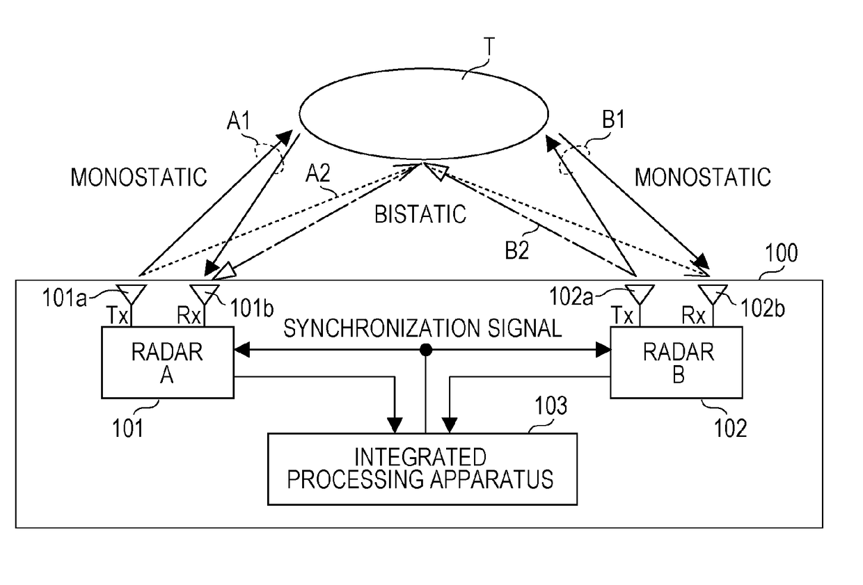
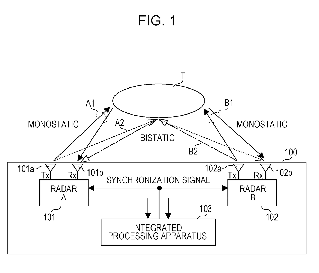
[0034]FIG. 1 schematically shows a relationship between a multi-radar system 100 according to a first embodiment of the present disclosure and a target T. As shown in FIG. 1, the multi-radar system 100 includes a radar A 101, a radar B 102, and an integrated processing apparatus 103.

[0035]The radar A 101 includes a transmitting antenna 101a and a receiving antenna 101b, and the radar B 102 includes a transmitting antenna 102a and a receiving antenna 102b. For reduction in size of the radar apparatuses, it is desirable that the transmitting antennas 101a and 102a and the receiving antennas 101b and 102b be located close to each other, respectively. For this reason, in the first embodiment, the transmitting antennas 101a and 102a and the receiving antennas 101b and 102b are placed, for example, at a distance of approximately 30λ or shorter from each other, respectively. It should be noted that λ is a wavelength that is determined by a ...

second embodiment

[0080]The first embodiment described above has described a case where the lines of sight of the radars A 101 and B 102 coincide with each other. A second embodiment described below describes a case where the lines of sight of the radars A 101 and B 102 do not coincide with each other.

[0081]FIG. 4 shows a block configuration of a multi-radar system 100a according to the second embodiment. As shown in FIG. 4, the multi-radar system 100a according to the second embodiment further includes a line-of-sight difference calculator 401, an other-radar position observer 402, a radar-B installation coordinate setter 403 in addition to the components of the multi-radar system 100 according to the first embodiment shown in FIG. 2.

[0082]The line-of-sight difference calculator 401 calculates shifts in the lines of sight of the radars A 101 and B 102 (a horizontal shift being hereinafter referred to as “θ”, a vertical shift being hereinafter referred to as “φ”). Shifts in the lines of sight may be ...

third embodiment

[0091]A multi-radar system 100b according to a third embodiment is configured to further include an average position calculator 501 as a further preferred example of the multi-radar system 100a according to the second embodiment. FIG. 5 shows a block configuration of the multi-radar system 100b according to the third embodiment.

[0092]The average position calculator 501 calculates an intensity-based average position on the basis of the positional information of the orthogonal coordinates of the radar A 101, the intensity vector of the radar A 101, the positional information of the orthogonal coordinates of the radar B 102, and the intensity vector of the radar B 102. Then, in a case where the output (intensity vector) from the phase synthesizer 241 is greater than the predetermined threshold, the threshold comparator 243 outputs the average position calculated by the average position calculator 501 to the position averager 245 as positional information. With this, in a case where rel...


PUM


Abstract

A multi-radar system is configured such that radars A and B perform synchronization so that their transmission timings and frequency bands are substantially the same. For this reason, in a case where the radars A and B operate as bistatic radars, the radars A and B yield the same detection results from reflected waves from a place on a surface of a target T where the detection object regions of the radars A and B overlap. Therefore, the signal-to-noise ratio can be improved by synthesizing the target detection results obtained by the radars A and B operating as bistatic radars. This results in improved target detection performance.

Description

BACKGROUND1. Technical Field[0001]The present disclosure relates to a multi-radar system including a plurality of radar apparatuses.2. Description of the Related Art[0002]Conventionally, a multi-radar system including a plurality of radar apparatuses has been proposed (see, for example, Japanese Patent No. 3643871). In this multi-radar system, adjacent radar apparatuses perform electronic beam scanning and have their phased-array antennas synchronized. At a timing when the adjacent radar apparatuses have such sensing object regions as to be operable as bistatic radars, they operate as bistatic radars, and at a timing where the adjacent radar apparatuses have such sensing object regions as to be hardly operable as bistatic radars, they operate as simple monostatic radars. The multi-radar system disclosed in Japanese Patent No. 3643871, for example when constituted by three or more radars, can secure a sufficient area of crossing of beams by synchronizing adjacent radars with each oth...

Claims


Application Information

Patent Timeline
Patent Type & Authority Applications(United States)
IPC IPC(8): G01S13/00H04B7/08
CPCG01S13/003H04B7/086G01S3/50G01S3/143G01S7/02G01S7/003G01S13/878G01S7/4082
Inventor YOMO, HIDEKUNIMATSUOKA, AKIHIKOIWASA, KENTA
Owner PANASONIC CORP
Why Eureka
Try Eureka