Image classification by brain computer interface

a brain computer and image technology, applied in the field of brain computer interfaces, can solve the problems of heavy computational demands and less suitable for real-time applications

Active Publication Date: 2018-03-29
INNEREYE
View PDF6 Cites 51 Cited by
  • Summary
  • Abstract
  • Description
  • Claims
  • Application Information

AI Technical Summary

Benefits of technology

[0028]According to some embodiments of the invention the invention the method c

Problems solved by technology

While non-linear classifiers have the potential to capture complex discriminative functions, their complexity can

Method used


Image

  • Image classification by brain computer interface
  • Image classification by brain computer interface
  • Image classification by brain computer interface

Examples


example 1

Album

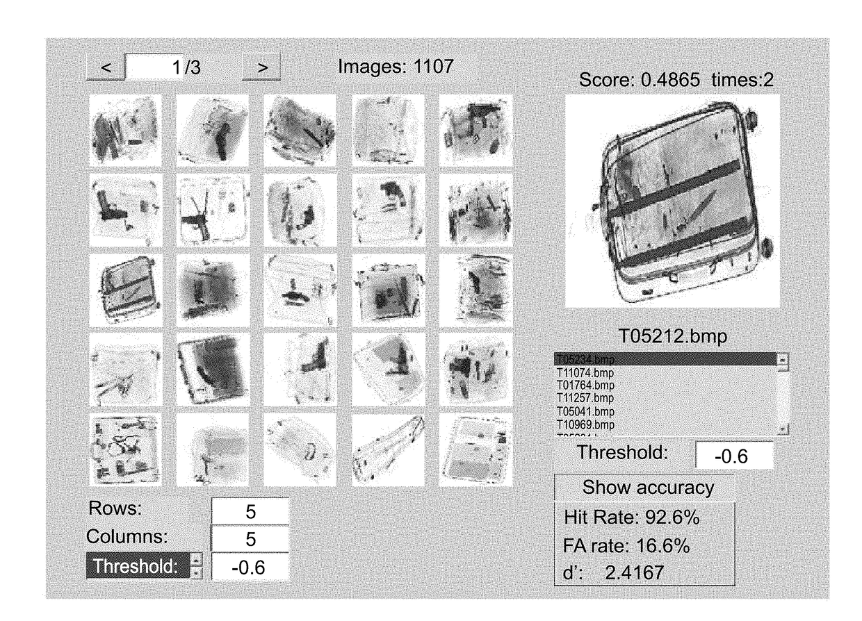
[0275]To classify a stack of individual images (e.g. X-ray images of baggage or medical images) the system of the present embodiments can arrange the images in an album (see representative screen shot in FIG. 7). Every image is given a score by the EEG classifier. The images are of the present embodiments sorted by their scores. In some embodiments of the present invention only images whose scores exceed a certain threshold Tare presented on the screen and classified as targets. The threshold T can be adjusted by the user in real time.

Example 2

Spatial “Heat Map”

[0276]For large images such as maps, satellite footage or aerial footage, it is beneficial to use the system of the present embodiments for generating a heat map (see representative screen shot in FIG. 8). In these embodiments the image is dissected to tiles with an overlap between adjacent tiles both in the x and y directions. The overlap is optionally and preferably such that a fraction p of the tile is shared with the...

example 2

X-Ray / CT Images

[0279]X-Ray / CT images of baggage or cargo, and medical X-Ray / CT images can be inspected using the system of the present embodiments. The prototype system described in Example 1 was successfully used to classify X-Ray images of airport checkpoint baggage to detect images containing threats (firearms and sharp objects). Following are the results of the experiment.

Brain Responses: ERP—Event Related Potentials and Spatial Distributions

[0280]FIG. 9A shows the average brain response (ERP) to targets and non-targets at one of the EEG electrodes (Pz). FIG. 9B presents the distribution of electrical potentials on the head 400-800 milliseconds after image presentation. Reddish colors indicate high energy which is useful for classification.

[0281]FIGS. 10A and 10B demonstrate the difference between brain responses to single images of Targets and Non-Targets measured at electrode Pz:

Scores Distribution

[0282]Every image was assigned with a classification score. FIG. 11 demonstrates...

example 3

Face Detection

[0290]The prototype system described in Example 1 was successfully tested to detect images of certain person face among other faces images.

[0291]Although the invention has been described in conjunction with specific embodiments thereof, it is evident that many alternatives, modifications and variations will be apparent to those skilled in the art. Accordingly, it is intended to embrace all such alternatives, modifications and variations that fall within the spirit and broad scope of the appended claims.

[0292]All publications, patents and patent applications mentioned in this specification are herein incorporated in their entirety by reference into the specification, to the same extent as if each individual publication, patent or patent application was specifically and individually indicated to be incorporated herein by reference. In addition, citation or identification of any reference in this application shall not be construed as an admission that such reference is av...


PUM


Abstract

A method of classifying an image is disclosed. The method comprises: applying a computer vision procedure to the image to detect therein candidate image regions suspected as being occupied by a target; presenting to an observer each candidate image region as a visual stimulus, while collecting neurophysiological signals from a brain of the observer; processing the neurophysiological signals to identify a neurophysiological event indicative of a detection of the target by the observer; and determining an existence of the target in the image is based, at least in part, on the identification of the neurophysiological event.

Description

RELATED APPLICATION[0001]This application claims the benefit of priority of Israeli Patent Application No. 239191 filed Jun. 3, 2015, the contents of which are incorporated herein by reference in their entirety.FIELD AND BACKGROUND OF THE INVENTION[0002]The present invention, in some embodiments thereof, relates to a Brain Computer Interface (BCI) and, more particularly, but not exclusively, to a method and system for classification of an image.[0003]BCI applications depend on decoding brain activity in response to single events (trials), as opposed to delineation of the average response frequently studied in basic research. Electroencephalography (EEG), a noninvasive recording technique, is one of the commonly used systems for monitoring brain activity. EEG data is simultaneously collected from a multitude of channels at a high temporal resolution, yielding high dimensional data matrices for the representation of single trial brain activity. In addition to its unsurpassed temporal ...

Claims


Application Information

Patent Timeline
IPC IPC(8): G06K9/46G06K9/62G06K9/20A61B5/11A61B5/0484A61B5/00A61B5/04G06V10/25G06V10/764G16H20/70G16H30/40
CPCG06K9/4628G06K9/627G06K9/2054A61B5/1103A61B5/04842A61B5/7264A61B5/04017A61B5/486G06F3/015G06N3/04G06N3/08G16H30/40G06N3/088G06N20/10G16H20/70G06V10/25G06V10/454G06V10/763G06V10/82G06V10/764G06V10/7715G06N7/01G06N3/045G06F2218/12G06F3/01A61B5/316A61B5/378A61B5/24G06V20/20G06F18/2135G06F18/2413G06F18/24137G06F2218/00
Inventor GEVA, AMIR B.DEOUELL, LEON Y.VAISMAN, SERGEYHARISH, OMRIMANOR, RAN EINETZER, EITANSHALGI, SHANI
Owner INNEREYE
Why Eureka
Try Eureka