Ablation catheter tip with flexible electronic circuitry

a technology of electronic circuitry and catheter tip, which is applied in the field of low thermal mass ablation catheter tip, can solve the problems of too low power setting and watts to create lesions, and achieve the effects of reducing tissue overheating, facilitating near real-time temperature sensing, and high thermal sensitivity

Pending Publication Date: 2018-04-05
ST JUDE MEDICAL CARDILOGY DIV INC
View PDF1 Cites 32 Cited by
  • Summary
  • Abstract
  • Description
  • Claims
  • Application Information

AI Technical Summary

Benefits of technology

[0007]It is desirable to be able to control the delivery of RF energy to a catheter to enable the creation of lesions in tissue by keeping the generator power setting sufficiently high to form adequate lesions while mitigating against overheating of tissue. Accordingly, aspects of the present disclosure are directed toward an ablation catheter tip including high thermal sensitivity materials which facilitate near real-time temperature sensing at the ablation catheter tip.

Problems solved by technology

This can, however, create problems in that such lower power settings (e.g., 15 Watts) may be too low to create lesions that are deep enough to be effective for treating abnormal heart rhythms.

Method used


Image

  • Ablation catheter tip with flexible electronic circuitry
  • Ablation catheter tip with flexible electronic circuitry
  • Ablation catheter tip with flexible electronic circuitry

Examples


Embodiment Construction

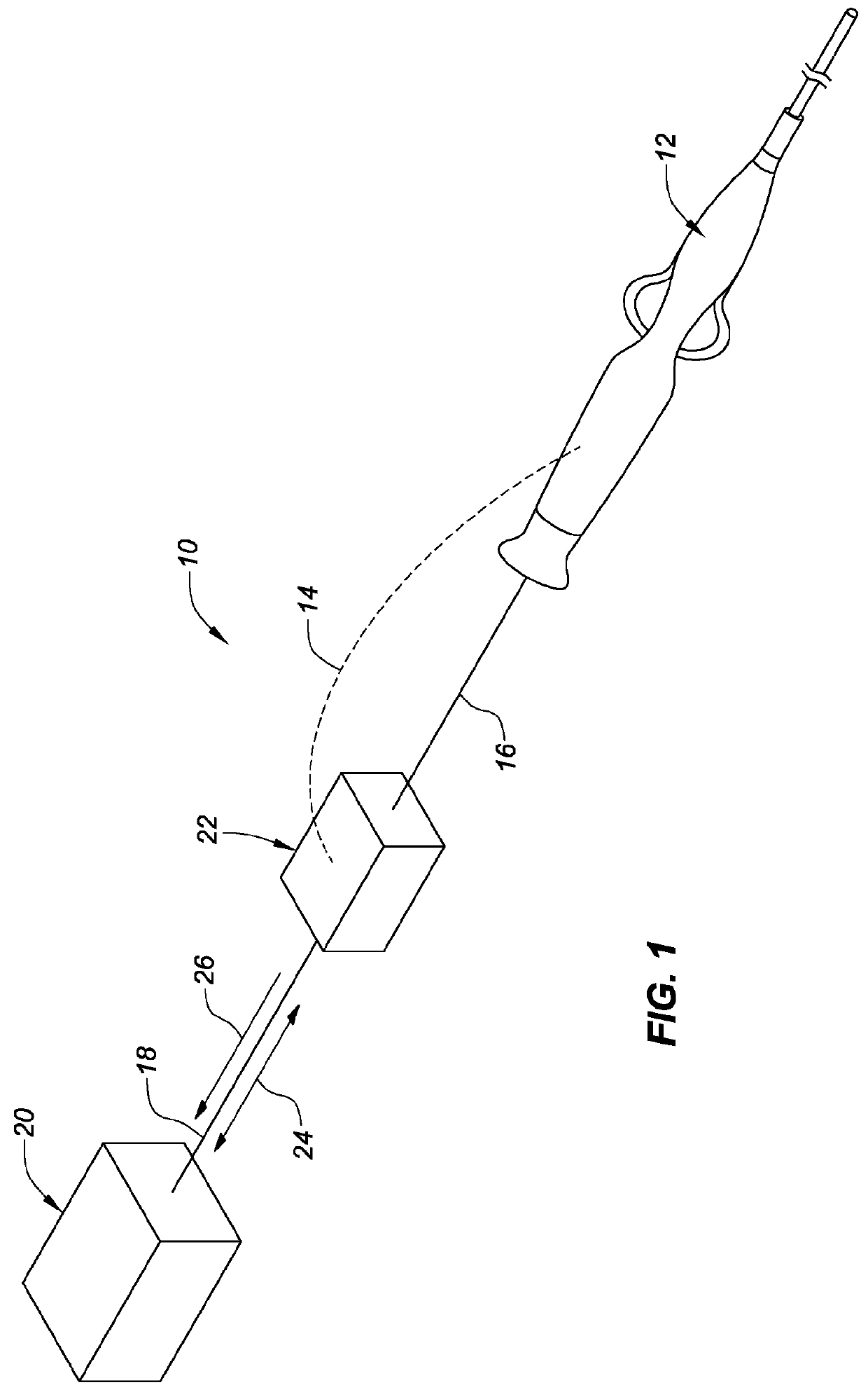
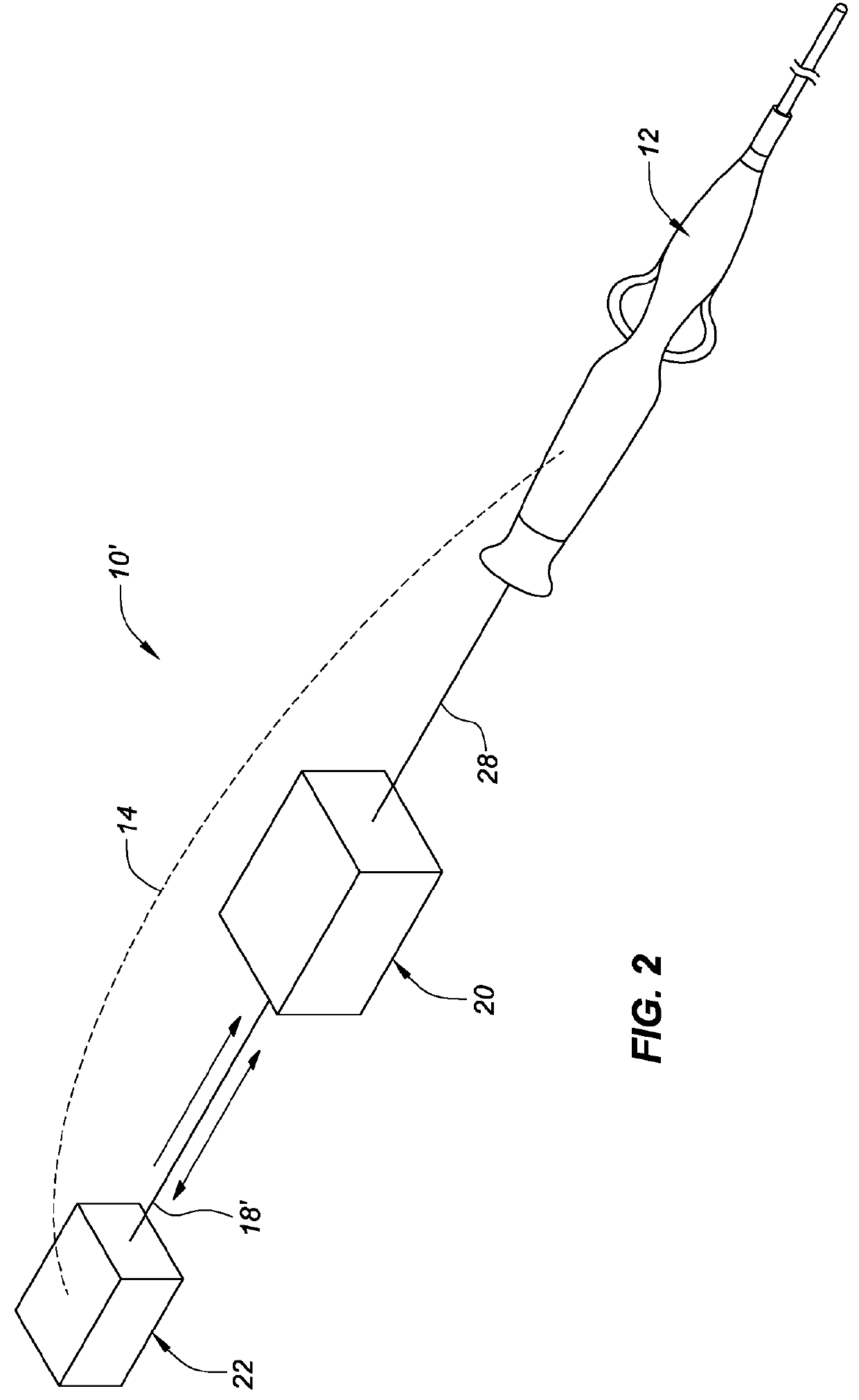
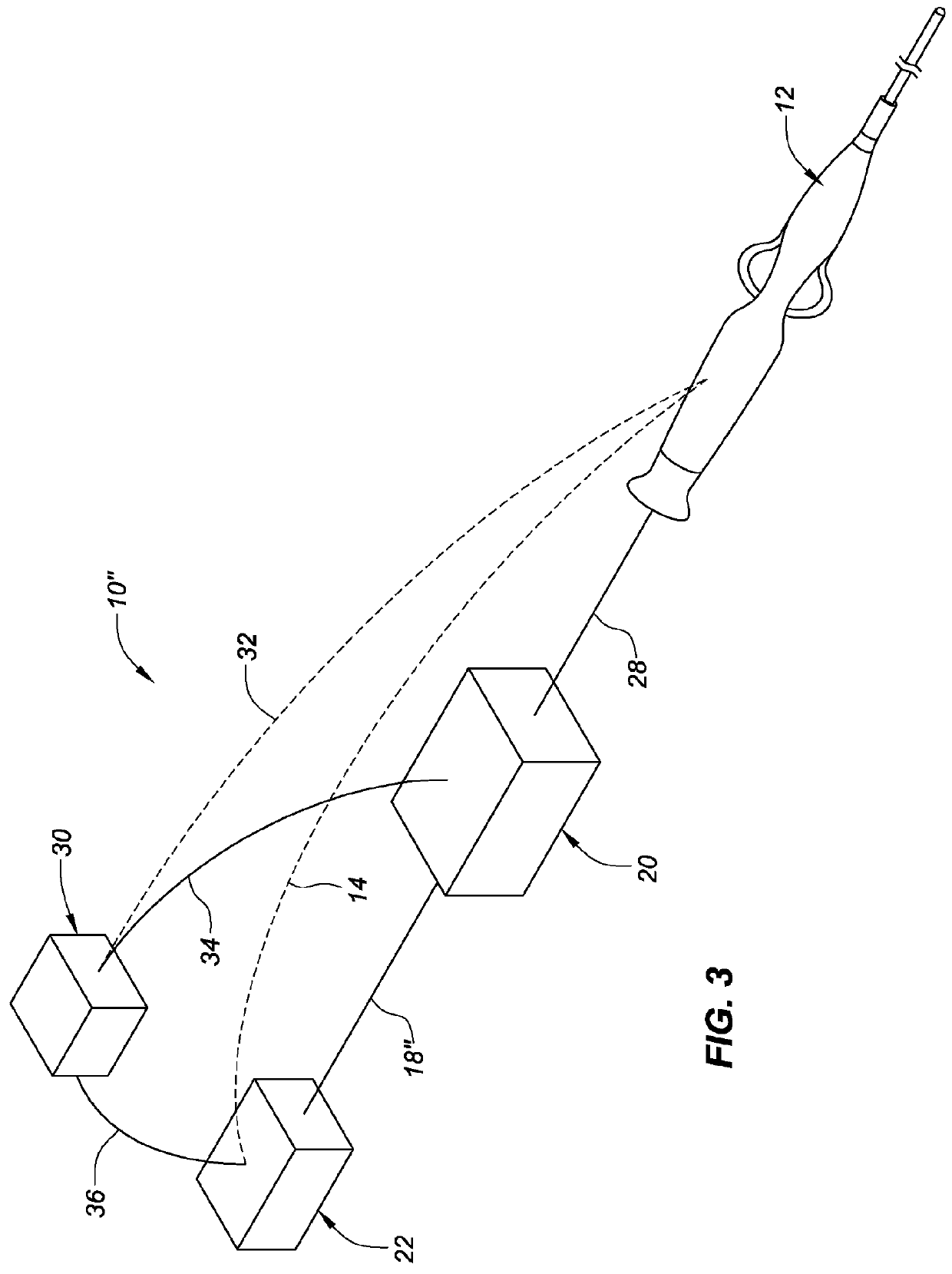
[0053]FIG. 1 is a highly-schematic representation of one embodiment of a system 10 for delivering pulsed RF energy to an ablation catheter 12 during catheter ablation, showing possible communication pathways 14, 16, 18 between primary components in this embodiment. This figure depicts a generator 20 operatively connected to a pulse control box 22, which is operatively connected to the ablation catheter 12. In this figure, a number of possible wired and / or wireless communication pathways are shown. For example, a dashed line 14 represents temperature feedback from the catheter to the pulse control box 22 of readings from at least one temperature sensor mounted in the tip of the catheter 12. In this embodiment, and in all of the embodiments described herein, the catheter may comprise multiple thermal sensors (for example, thermocouples or thermistors), as described further below. If the catheter comprises multiple temperature sensors mounted in its tip region, the feedback shown in FI...


PUM


Abstract

Aspects of the present disclosure are directed to, for example, a high-thermal-sensitivity ablation catheter tip including a thermally-insulative ablation tip insert supporting at least one temperature sensor electrically coupled to a flexible electronic circuit and encapsulated, or essentially encapsulated, by a conductive shell. Also disclosed is a method of controlling the temperature of an ablation catheter tip while creating a desired lesion using various forms of energy and energy delivery.

Description

CROSS-REFERENCE TO RELATED APPLICATIONS[0001]This application claims the benefit of U.S. provisional application No. 62 / 517,594, filed 9 Jun. 2017, and which is hereby incorporated by reference as though fully set forth herein.[0002]This application claims the benefit of U.S. provisional application Nos. 62 / 404,060, 62 / 404,038, and 62 / 404,013, all of which were filed 4 Oct. 2016, which are hereby incorporated by reference as though fully set forth herein.[0003]This application incorporates by reference as though fully set forth herein, U.S. application Ser. No. 15 / 088,036, filed 31 Mar. 2016, now pending, which claims the benefit of U.S. provisional application No. 62 / 141,066, filed 31 Mar. 2015; U.S. application Ser. No. 15 / 088,052, filed 31 Mar. 2016, now pending, which claims the benefit of U.S. provisional application No. 62 / 198,114, filed 28 Jul. 2015.BACKGROUND OF THE DISCLOSUREa. Field[0004]The present disclosure relates to low thermal mass ablation catheter tips (also known ...

Claims


Application Information

Patent Timeline
Patent Type & Authority Applications(United States)
IPC IPC(8): A61B18/14A61B5/042A61B8/12A61B5/361A61B5/364
CPCA61B18/1492A61B5/0422A61B8/12A61B5/0468A61B18/24A61B2018/00839A61B2018/00351A61B2018/00577A61B2018/00101A61B2017/00154A61B2018/00708A61B2018/00791A61B2018/00797A61B2218/002A61B5/4848A61B5/287A61B5/361A61B5/364A61B2018/00077A61B2018/00095A61B18/18A61B2018/00642A61B2017/00221
Inventor TEGG, TROY T.
Owner ST JUDE MEDICAL CARDILOGY DIV INC
Why Eureka
Try Eureka