Backlight module and liquid crystal display

a backlight module and liquid crystal display technology, applied in non-linear optics, instruments, optics, etc., can solve the problem of reducing the light control ability of the liquid crystal display device, and achieve the effect of increasing the light control ability of the liquid crystal display and increasing the dynamic contrast ratio of the displayed pictur

Inactive Publication Date: 2018-04-12
TCL CHINA STAR OPTOELECTRONICS TECH CO LTD
View PDF3 Cites 1 Cited by
  • Summary
  • Abstract
  • Description
  • Claims
  • Application Information

AI Technical Summary

Benefits of technology

[0024]The beneficial effects of the present invention are: comparing to the conventional art, the backlight module of the present invention comprises a back plate and a light source, wherein, the back plate includes multiple concave units arranged as a matrix; and the light source disposed at an inner bottom surface of each concave unit. The present invention can avoid a mutual interference of light between adjacent two concave units, capable of increasing the light controlling ability of the liquid crystal display and increasing the dynamic contrast ratio of a displayed picture.

Problems solved by technology

However, among the light sources, a mutual interference is easily generated such that a light controlling ability of the liquid crystal display device is decreased so as to decrease a dynamic contrast ratio of the liquid crystal display device.

Method used


Image

  • Backlight module and liquid crystal display
  • Backlight module and liquid crystal display
  • Backlight module and liquid crystal display

Examples


first embodiment

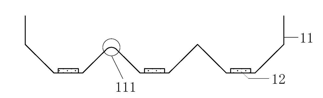
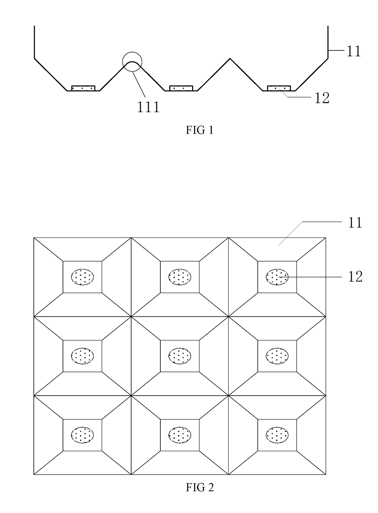
[0031]With reference to FIG. 1, and FIG. 1 is a side view of a structure of a backlight module of the present invention. The backlight module includes a back plate 11 and a light source 12. The back plate 11 includes multiple concave units arranged as a matrix. The light source 12 is disposed at a bottom surface of each concave unit.

[0032]Optionally, the back plate 11 can be made of a metal material such as aluminum or aluminum alloy that has a good thermal conductivity. Besides, the back plate 11 can also be made of a plastic material, and the back plate made of the plastic material has features of light weight and low cost.

[0033]The back plate 11 includes multiple concave units arranged as a matrix. It can be understood that the back plate 11 is formed integrally. Every adjacent two concave units are formed integrally. Optionally, the back plate 11 and the concave units are formed through stamping once. In another embodiment, the back plate 11 and the concave units can be formed b...

second embodiment

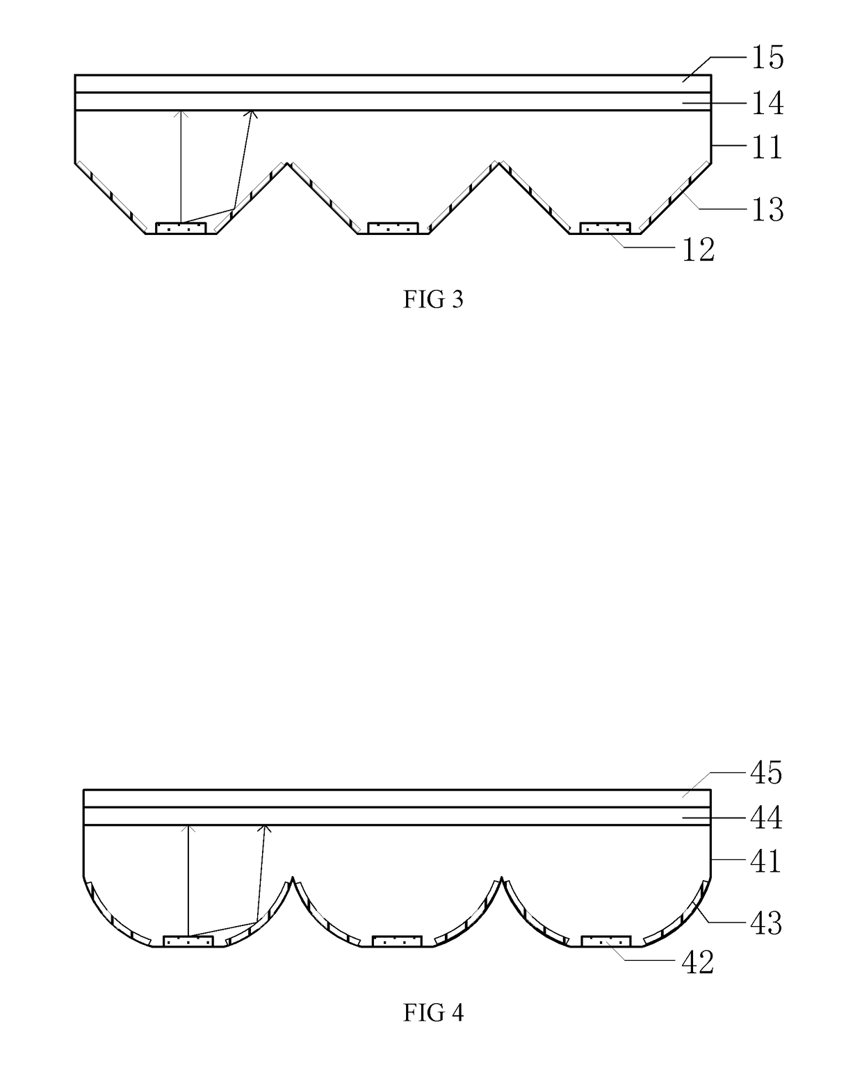
[0050]With reference to FIG. 4, which is a side view of a structure of a backlight module of the present invention. The backlight module of the present embodiment includes a back plate 41, a light source 42, a reflective sheet 43, a diffusion plate 44 and an optical film 45.

[0051]Wherein, the back plate 41 includes multiple concave units arranged as a matrix, the light source 42 is disposed at a bottom surface of each concave unit. The reflective sheet 43 is disposed at side surfaces inside each concave unit. The diffusion sheet 44 is disposed above an opening of each concave unit. The optical film 45 is disposed at a side of the diffusion plate away from the concave units.

[0052]Specifically, in the present embodiment, each concave unit is surrounded and formed by multiple side surfaces and one bottom surface. An area of the opening of the concave unit is greater than an area of the bottom surface. The bottom surface of the concave unit is a circular flat surface, and the side surfa...


PUM

PropertyMeasurementUnit
areaaaaaaaaaaa
volumeaaaaaaaaaa
structureaaaaaaaaaa

Abstract

A backlight module and a liquid crystal display are disclosed. The backlight module includes: a back plate including multiple concave units arranged as a matrix; and a light source disposed at an inner bottom surface of each concave unit. Through above way, the present invention is capable of increasing the light controlling ability of the liquid crystal display and increasing the dynamic contrast ratio of the displayed picture.

Description

BACKGROUND OF THE INVENTION1. Field of the Invention[0001]The present invention relates to a display technology, and more particularly to a backlight module and a liquid crystal display.2. Description of Related Art[0002]In a conventional TFT-LCD (thin film transistor-liquid crystal display), because, a TFT-LCD panel does not emit light itself, an additional light source is required to perform a display. Usually, two types of light sources, a backlight type light source and a reflective type light source are provided. Because the backlight type light source will not be affected by the environment so that the light source in the TFT-LCD is almost a backlight type light source currently.[0003]In the backlight source of the TFT-LCD, the light source becomes an LED (Light Emitting Diode) light source from a CCFL (Cold Cathode Fluorescent Lamp) light source. Because the LED has many advantages of small volume, fast response time, long life, non-friable, high color gamut, many kinds of pa...

Claims


Application Information

Patent Timeline
Patent Type & Authority Applications(United States)
IPC IPC(8): G02F1/1335G02F1/1333
CPCG02F1/133603G02F1/133308G02F1/133608G02F1/133605G02F2001/133314G02F1/133314
Inventor FAN, YONG
Owner TCL CHINA STAR OPTOELECTRONICS TECH CO LTD
Why Eureka
Try Eureka