
Apparatus and method for powering a coil of latching relays and hybrid switches

a technology of latching relays and hybrid switches, applied in the direction of electromagnetic relays, electrical apparatus, electromagnetic relay details, etc., can solve the problem of substantial over-all consumption of power

Active Publication Date: 2020-03-10
ELBEX VIDEO LTD
View PDF34 Cites 0 Cited by
  • Summary
  • Abstract
  • Description
  • Claims
  • Application Information

AI Technical Summary

Benefits of technology

The invention relates to a new way of controlling the switching of electrical devices connected to manual and remote switches. The system includes a single latching switch and a base floor controller, with other floors using manual switches. The goal is to improve the control of lighting and appliances in buildings, especially at entrances and staircases. The invention focuses on reducing the force needed to operate the switch and simplifying the mechanism for latching and releasing, as well as minimizing the power consumed by the switch. Various solutions are proposed, such as reducing the contact pressure variations and using a compressed spring or controlled power feed. Another aspect of the invention involves using a simplified slider and a guided lock pin, or using an exponentially dimming voltage to stabilize the armature during the latching and release processes. Overall, the invention improves the efficiency and convenience of controlling electrical devices in buildings.

Problems solved by technology

Many relays installed in a residence or in a shop, or in a factory, or in public facilities persistently drain current and consumed power, thus when many such automation system are installed the overall consumed power will be substantial.

Method used


Image

  • Apparatus and method for powering a coil of latching relays and hybrid switches
  • Apparatus and method for powering a coil of latching relays and hybrid switches
  • Apparatus and method for powering a coil of latching relays and hybrid switches

Examples


Embodiment Construction

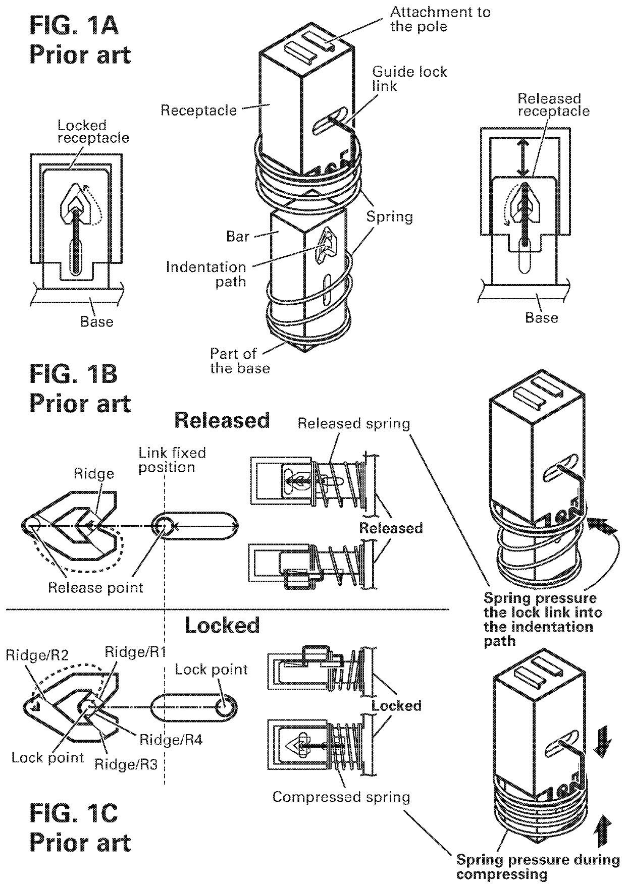
[0066]FIGS. 1A, 1B and 1C show the known lock-release device of the prior art as used for push switches and applied to latching relays and hybrid switches. The lock-release shown is also known as mechanical latching of relays and are shown in the referenced US patents for manual push-keys for a switch and relay combinations. The known mechanism is commonly embedded into a key bar individually and the use of a similar latching structure for latching the SPDT relay pole or dual poles of the DPDT relay was a novel structure for latching a relay pole of the U.S. Pat. No. 9,257,251.

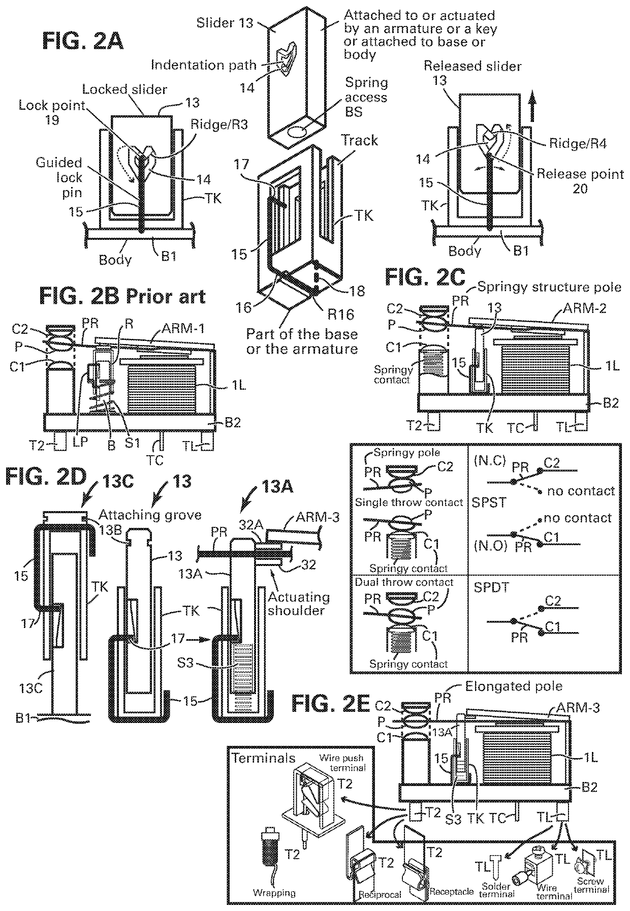
[0067]FIG. 1A showing the prior art mechanism, introduced to explain the features created by combining the very simple lock-release to a structure shown in FIG. 2B of the prior art that is attached to the relay pole that is loosely attached to armature ARM-1 of FIG. 2B and to a receptacle R. The receptacle R and the bar B are linked via the rigid guided lock link LP pressured by a released spring S1 while pres...


PUM


Abstract

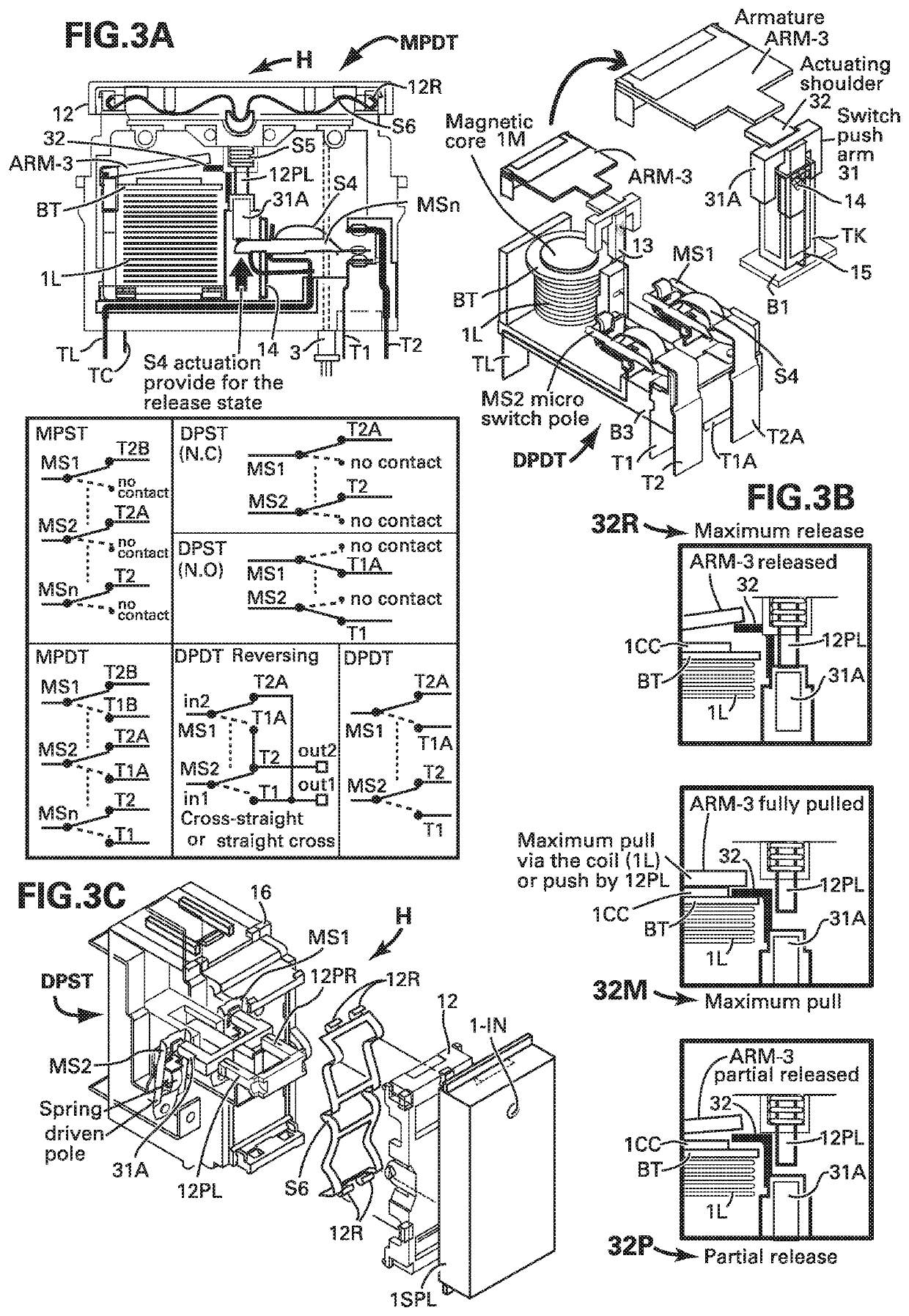
Apparatus and method for latching one pole contact of at least one springy pole in one of a relay and an hybrid switch for maintaining one of engaging and disengaging state of at least one first contact with said pole contact by a mechanical latching device comprising a springy lock pin exerting minute force, a slider with indentation path for guiding the lock pin and a track for the slider, the latching device extends from an armature or the springy pole to a base or a body of the relay or the hybrid switch, said springy pole is guided by said slider movement propelled by one of a pull by a voltage rated magnetic coil fed by a pulse of said rated voltage and a push by a plunger, and for operating a stronger coil for switching higher electrical current the magnetic coil is fed with combination with at least one discharge higher voltage to increase the magnetic pull power of the coil.

Description

RELATED APPLICATION[0001]This application is a continuation-in-part of U.S. application Ser. No. 15 / 171,339, filed on Jun. 2, 2016, and now allowed, which is incorporated herein by reference.BACKGROUND OF THE INVENTION[0002]1. Field of the Invention[0003]This invention is related to powering of magnetic coils used to actuate mechanical latching hybrid switches and relays and for reducing the needed force to operate the mechanical latching.[0004]2. Description of the Prior Art[0005]Switches and relays for switching on-off electrical appliances such as water boiler, air conditioners, heaters, lights and any other electrical equipment and appliances in residences, offices, public building, businesses, restaurants and factories are very well known. The well known relay devices for home automation are commonly installed in the main or a sub electrical cabinet of a given premises. The installed relays are operated via bus lines, RF, or by control signal propagated via the AC power line.[0...

Claims


Application Information

Patent Timeline
Patent Type & Authority Patents(United States)
IPC IPC(8): H01H9/20H01H50/14H01H51/08H01H47/22H01H50/44H01H50/54H01H50/64H01H50/32H01H47/32H01H50/24
CPCH01H50/32H01H50/44H01H50/54H01H51/08H01H50/14H01H50/643H01H50/326H01H47/22H01H50/24H01H2235/01H01H47/32
Inventor ELBERBAUM, DAVID
Owner ELBEX VIDEO LTD
Learn More