Optical image capturing system

a technology of optical image and capturing system, which is applied in the field of compact can solve the problems of affecting the design and manufacture of miniaturized surveillance cameras in the future, occupying a large space for the elements of the icr, and being expensive, so as to achieve the effect of reducing the height of the optical system, avoiding undesired generation of aberration, and avoiding aberration of the optical image capturing system

Inactive Publication Date: 2018-04-19
ABILITY OPTO ELECTRONICS TECH
View PDF10 Cites 16 Cited by
  • Summary
  • Abstract
  • Description
  • Claims
  • Application Information

AI Technical Summary

Benefits of technology

[0052]The height of optical system (HOS) may be reduced to achieve the minimization of the optical image capturing system when the absolute value of f1 is larger than the absolute value of f7 (|f1|>|f7|).
[0053]When the conditions of |f2|+|f3|+|f4|+|f5|+|f6| and |f1|+|f7| satisfy the aforementioned condition, at least one of the second through sixth lens elements may have weak positive refractive power or weak negative refractive power. The weak refractive power indicates that an absolute value of the focal length of a specific lens element is greater than 10. When at least one of the second through sixth lens elements has the weak positive refractive power, the positive refractive power of the first lens element can be shared, so as to avoid...

Problems solved by technology

Nevertheless, the elements of the ICR occupy a significant amount of space and are expensiv...

Method used


Image

  • Optical image capturing system
  • Optical image capturing system
  • Optical image capturing system

Examples


first embodiment

The First Embodiment

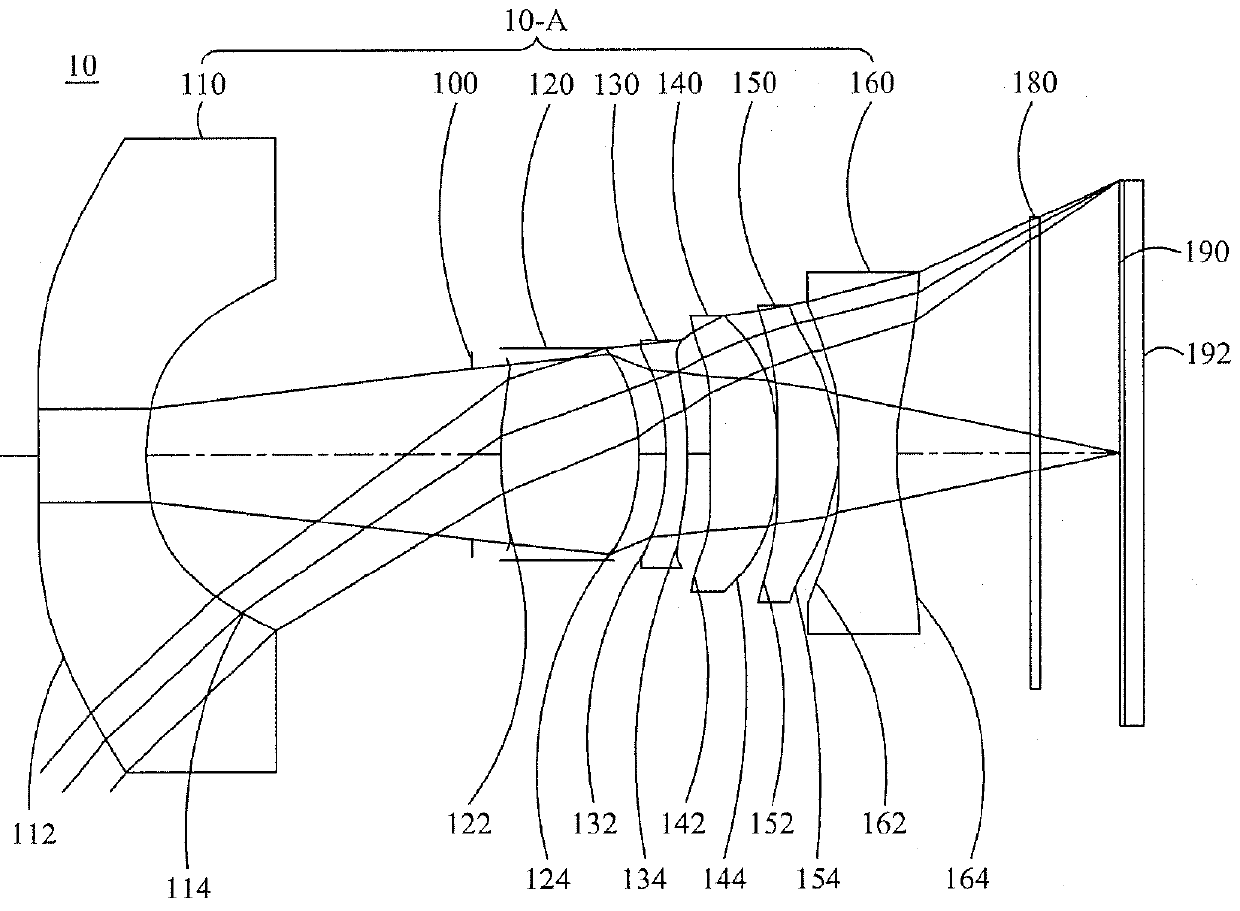
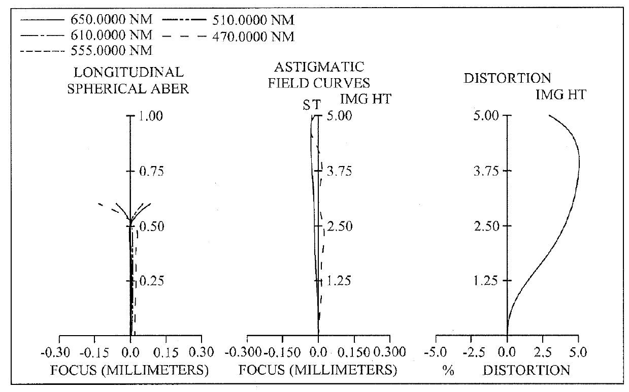
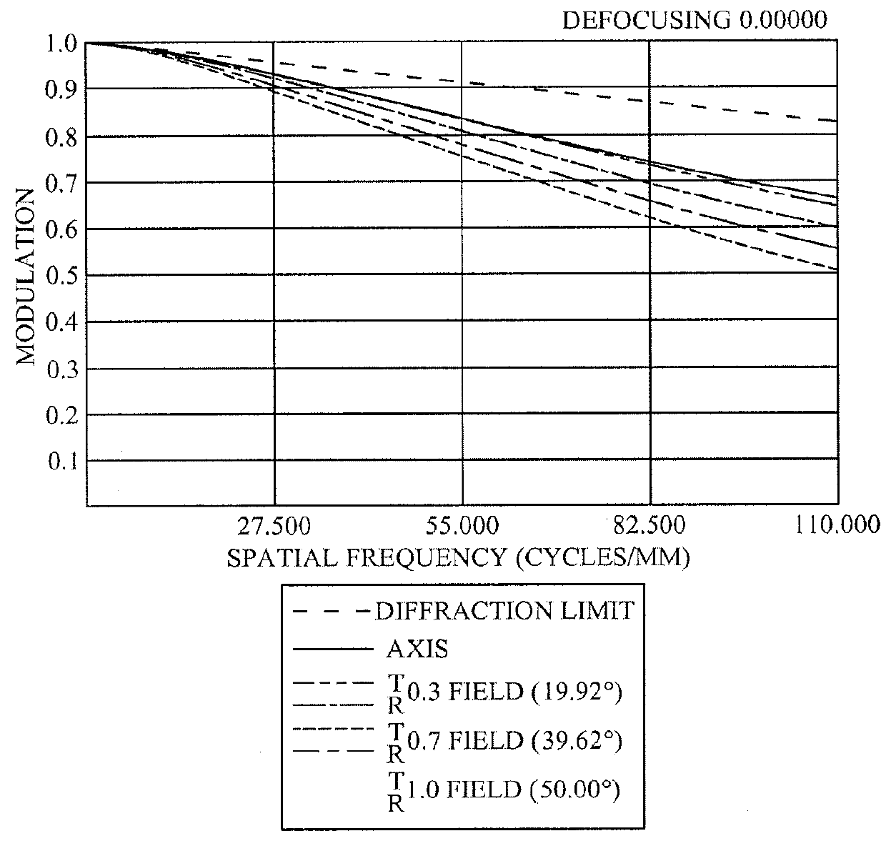
[0127]Please refer to FIGS. 1A to 1E. FIG. 1A is a schematic view of the optical image capturing system according to the first embodiment of the present invention. The optical image capturing system may include an imaging lens assembly 10-A having six lens elements with refractive powers, which may focus both visible and infrared lights to form high quality images. FIG. 1B shows the longitudinal spherical aberration curves, astigmatic field curves, and optical distortion curve of the optical image capturing system in the order from left to right according to the first embodiment of the present invention. FIG. 1C is a characteristic diagram of modulation transfer of the visible light according to the first embodiment of the present application. FIG. 1D is a diagram showing the through-focus MTF values of the visible light spectrum at the central field of view, 0.3 field of view, and 0.7 field of view of the first embodiment of the present invention. FIG. 1E is a d...

second embodiment

[0198]Please refer to FIGS. 2A to 2E. FIG. 2A is a schematic view of the optical image capturing system according to the second embodiment of the present invention. The optical image capturing system may include an imaging lens assembly 20-A having seven lens elements with refractive powers, which may focus both visible and infrared lights to form high quality images. FIG. 2B shows the longitudinal spherical aberration curves, astigmatic field curves, and optical distortion curve of the optical image capturing system of the second embodiment, in the order from left to right. FIG. 2C is a characteristic diagram of modulation transfer of the visible light according to the second embodiment of the present application. FIG. 2D is a diagram showing the through-focus MTF values of the visible light spectrum at the central field of view, 0.3 field of view, and 0.7 field of view of the second embodiment of the present invention. FIG. 2E is a diagram showing the through-focus MTF values of t...

third embodiment

[0211]Please refer to FIGS. 3A to 3E. FIG. 3A is a schematic view of the optical image capturing system according to the third embodiment of the present invention. The optical image capturing system may include an imaging lens assembly 30-A having six lens elements with refractive powers, which may focus both visible and infrared lights to form high quality images. FIG. 3B shows the longitudinal spherical aberration curves, astigmatic field curves, and optical distortion curve of the optical image capturing system, in the order from left to right, according to the third embodiment of the present invention. FIG. 3C is a characteristic diagram of modulation transfer of the visible light according to the third embodiment of the present application. FIG. 3D is a diagram showing the through-focus MTF values of the visible light spectrum at the central field of view, 0.3 field of view, and 0.7 field of view of the third embodiment of the present invention. FIG. 3E is a diagram showing the...


PUM


Abstract

An optical image capturing system including an imaging lens assembly having at least three lens elements for capturing image is provided. The optical image capturing system includes at least three pieces of lens elements; a first image plane for visible ray; a second image plane for infrared ray; and an image sensing device located between the first image plane the second image plane. The distance on the optical axis can be minimized by the design of said optical lens elements to improve the imaging quality of both visible ray and infrared ray in compact cameras.

Description

CROSS-REFERENCE TO RELATED APPLICATION[0001]This application claims priority from Taiwan Patent Application No. 105133768, filed on Oct. 19, 2016, at the Taiwan Intellectual Property Office, the content of which is hereby incorporated by reference in its entirety for all purposes.BACKGROUND OF THE INVENTION1. Field of the Invention[0002]The present disclosure relates to an optical image capturing system, and more particularly to a compact optical image capturing system which can be applied to electronic products.2. Description of the Related Art[0003]In recent years, with the rise of portable electronic devices having camera functionalities, the demand for an optical image capturing system is raised gradually. The image sensing device of ordinary photographing camera is commonly selected from charge coupled device (CCD) or complementary metal-oxide semiconductor sensor (CMOS Sensor). In addition, as advanced semiconductor manufacturing technology enables the minimization of pixel si...

Claims


Application Information

Patent Timeline
IPC IPC(8): G02B7/02G02B27/00G02B27/12
CPCG02B7/02G02B27/0025G02B13/0015G02B9/12G02B27/123G02B13/0045G02B13/0035G02B13/004
Inventor CHANG, YEONG-MINGLAI, CHIEN-HSUNLIAO, KUO-YULIU, YAO-WEI
Owner ABILITY OPTO ELECTRONICS TECH
Why Eureka
Try Eureka