Computer program, object tracking method, and object tracking device

Active Publication Date: 2018-04-19
SEIKO EPSON CORP
View PDF7 Cites 22 Cited by
  • Summary
  • Abstract
  • Description
  • Claims
  • Application Information

AI Technical Summary

Benefits of technology

[0004]An advantage of some aspects of this disclosure is to improve the accuracy of tracking the 3D pose of an object.
[0005]The advantage can be achieved in the following configurations.
[0006]An aspect of the disclosure is directed to a non-transitory computer readable medium that embodies instructions that cause one or more processors to perform a method including: acquiring a first image of a scene including an object captured with a camera positioned at a first position; deriving a 3D pose of the object in a second image captured with the camera positioned at a second position using a 3D model c

Problems solved by technology

However, the 3D model being unknown is disadvantageous in tracking the

Method used


Image

  • Computer program, object tracking method, and object tracking device
  • Computer program, object tracking method, and object tracking device
  • Computer program, object tracking method, and object tracking device

Examples


Embodiment Construction

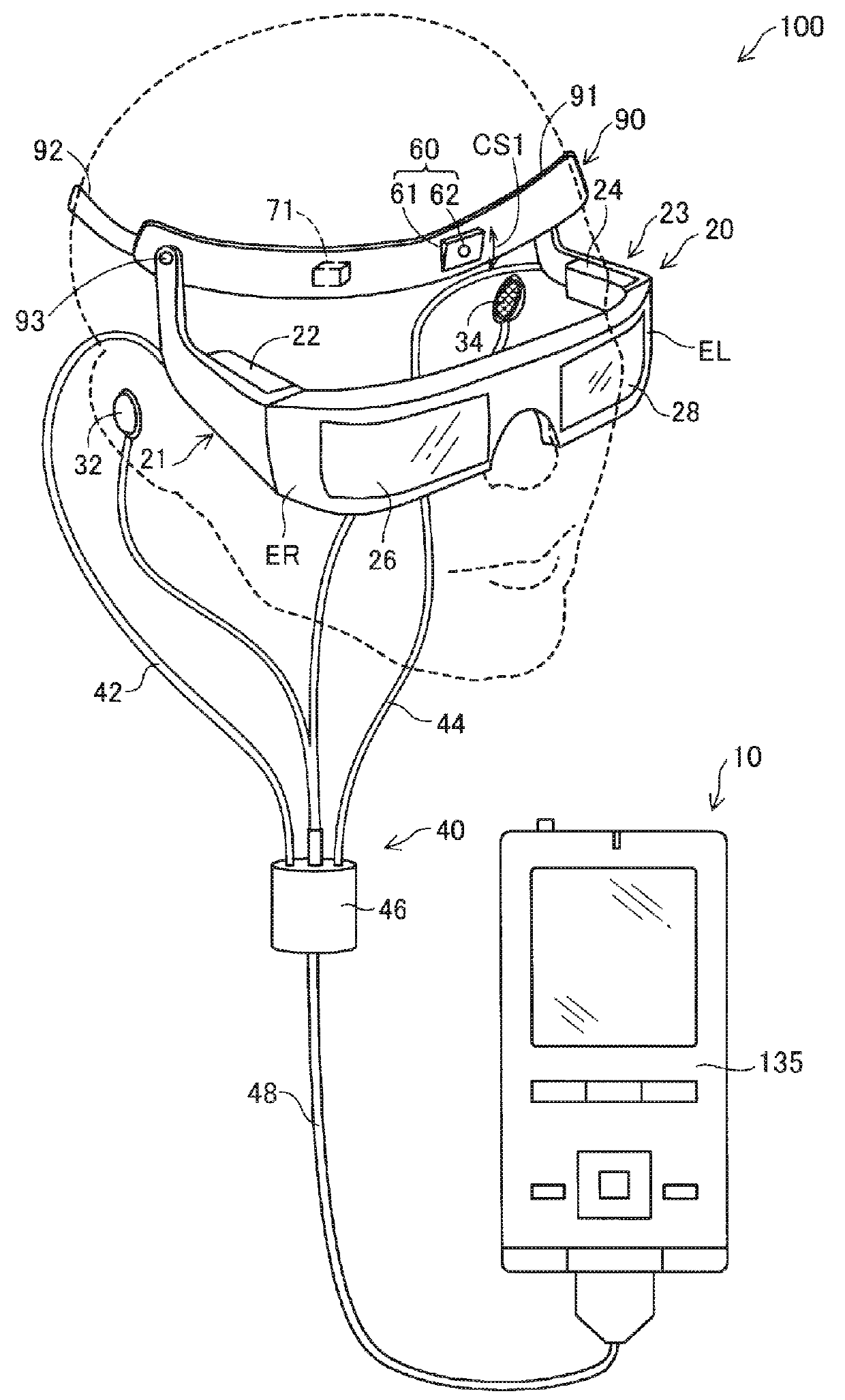
[0019]FIG. 1 shows the schematic configuration of an HMD 100. The HMD 100 is a head-mounted display. The HMD 100 is an optical transmitting-type device. That is, the HMD 100 can allow the user to perceive a virtual image and at the same time directly visually recognize light coming from the external scenery (scene) including an object. The HMD 100 functions as a tracking device which tracks an object, as described later.

[0020]The HMD 100 has an attachment strap 90 which can be attached to the head of the user, a display section 20 which displays an image, and a control section 10 which controls the display section 20. The display section 20 allows the user to perceive a virtual image in the state where the HMD 100 is mounted on the head of the user. The display section 20 allowing the user to perceive a virtual image is also referred to as “displaying AR”. The virtual image perceived by the user is also referred to as an AR image.

[0021]The attachment strap 90 includes a wearing base...


PUM


Abstract

A computer program causes an object tracking device to realize functions of: acquiring a first image of a scene including an object captured with a camera positioned at a first position; deriving a 3D pose of the object in a second image captured with the camera positioned at a second position using a 3D model corresponding to the object; deriving 3D scene feature points of the scene based at least on the first image and the second image; obtaining a 3D-2D relationship between 3D points represented in a 3D coordinate system of the 3D model and image feature points on the second image; and updating the derived pose using the 3D-2D relationship, wherein the 3D points include the 3D scene feature points and 3D model points on the 3D model.

Description

BACKGROUND1. Technical Field[0001]This disclosure relates to the tracking of an object.2. Related Art[0002]Renato F. Salas-Moreno, Richard A. Newcombe, Hauke Strasdat, Paul H. J. Kelly, Andrew J. Davison, “SLAM++: Simultaneous Localisation and Mapping at the Level of Objects,” CVPR (Conference on Computer Vision and Pattern Recognition) (United States), IEEE (Institute of Electrical and Electronics Engineers), 2013, p. 1352-1359 discloses SLAM. SLAM is the abbreviation of simultaneous localization and mapping and refers to a method of simultaneously realizing localization and environmental mapping.SUMMARY[0003]SLAM can be implemented on the assumption that a scene or a 3D model of an object included in the scene is unknown. However, the 3D model being unknown is disadvantageous in tracking the 3D object, that is, estimating the 3D pose of the object to the camera.[0004]An advantage of some aspects of this disclosure is to improve the accuracy of tracking the 3D pose of an object.[00...

Claims


Application Information

Patent Timeline
IPC IPC(8): G06T7/73G02B27/01
CPCG06T7/74G06T7/75G02B27/0172G06T2200/04G06F3/011G02B2027/014G02B2027/0138G06F3/0304G06T7/73G06T7/246
Inventor LEVINSHTEIN, ALEX
Owner SEIKO EPSON CORP
Why Eureka
Try Eureka