Unlock instant, AI-driven research and patent intelligence for your innovation.

Rotation sensor

a technology of rotating sensors and internal filling resin, which is applied in the direction of instruments, measurement apparatus components, measurement devices, etc., can solve the problems of high manufacturing cost and high filling cost of internal filling resin, and achieve the effect of reducing manufacturing cos

Active Publication Date: 2018-04-26
MITSUBISHI ELECTRIC CORP
View PDF1 Cites 0 Cited by
  • Summary
  • Abstract
  • Description
  • Claims
  • Application Information

AI Technical Summary

Benefits of technology

The present invention provides a rotation sensor that can reduce manufacturing cost. The sensor includes a holder that surrounds the magnetic detection section and is in cooperation with a case. The holder has a main body with a rib that is in contact with the lead frame's forming portion, allowing for the magnetic detection section to be fixed to the case without using an expensive internal filling resin. This results in a less expensive rotation sensor.

Problems solved by technology

However, in order to fix the magnetic detection section to the case, an expensive internal filling resin is filled into the internal space of the case.
Thus, there is a problem in that manufacturing cost is high.

Method used


Image

  • Rotation sensor
  • Rotation sensor
  • Rotation sensor

Examples


first embodiment

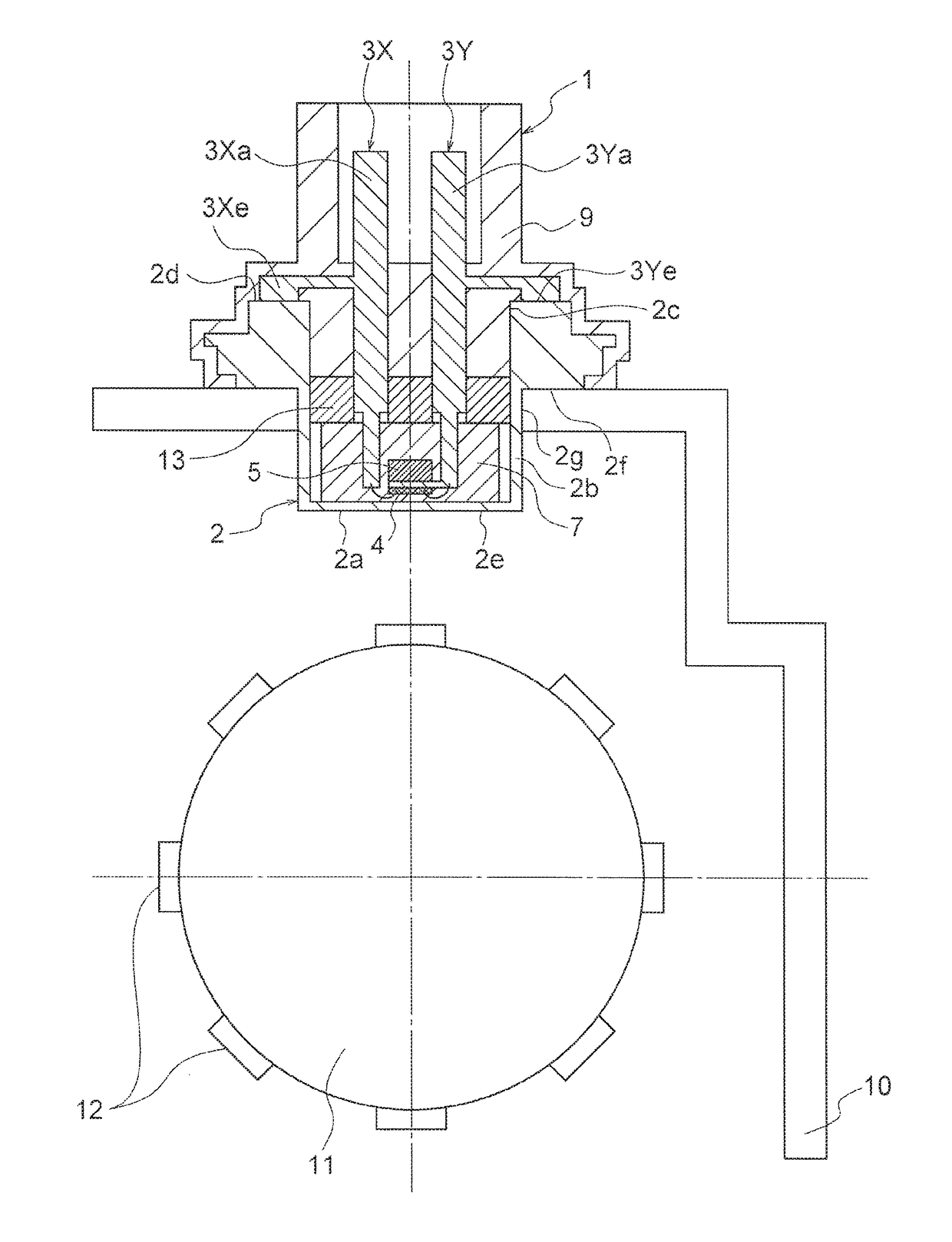
[0031]A rotation sensor according to a first embodiment of the present invention is to be used in, for example, an engine or a transmission of an automobile, and is configured to detect rotation of a rotating body. FIG. 1 is a sectional view for illustrating the rotation sensor according to the first embodiment of the present invention. FIG. 2 is an enlarged view for illustrating relevant parts of the rotation sensor of FIG. 1. FIG. 3 is a sectional view taken along the line III-III of FIG. 2. A rotation sensor 1 is inserted into an opening of a housing 10, and is mounted to the housing 10. In the housing 10, a rotary shaft 11 being the rotating body is accommodated. A joint shaft, which is connected to a crankshaft of an engine, or a crankshaft is exemplified as the rotary shaft 11. A plurality of convex portions 12 are arranged on an outer peripheral surface of the rotary shaft 11 at intervals along a circumferential direction of the rotary shaft 11. The convex portions 12 are mad...

second embodiment

[0049]FIG. 12 is a sectional view for illustrating a rotation sensor according to a second embodiment of the present invention. The case 2 includes an abutment surface 2h to be brought into abutment on the holder 13 in the depth direction B of the case 2. A surface of the holder 13 to be brought into abutment on the abutment surface 2h is referred to as a holder lower surface. The abutment surface 2h is arranged to be flush with a surface of the magnetic detection section 7 that is to be brought into abutment on the holder 13 in the depth direction B of the case 2. The surface of the magnetic detection section 7 to be brought into abutment on the holder 13 in the depth direction B of the case 2 is referred to as a magnetic detection section upper surface. The other components are the same as those of the first embodiment.

[0050]As described above, according to the rotation sensor 1 of the second embodiment of the present invention, the case 2 includes the abutment surface 2h to be br...

third embodiment

[0051]FIG. 13 is a sectional view for illustrating a rotation sensor according to a third embodiment of the present invention. The case 2 includes an inclined surface 2i formed so that a dimension of the internal space of the case 2 in the width direction A decreases as approaching to the bottom surface portion 2a in the depth direction B of the case 2. The inclined surface 2i is formed from the bottom surface portion 2a to the vicinity of the magnetic detection section upper surface of the magnetic detection section 7 in the inside of the case 2. In the vicinity of the magnetic detection section upper surface, an inner diameter of the case 2 is smaller than an outer diameter of the holder 13. At least a part of the outer peripheral surface 13e of the holder 13 is brought into abutment on the inclined surface 2i. The other components are the same as those of the first embodiment.

[0052]As described above, according to the rotation sensor 1 of the third embodiment of the present inven...


PUM


Abstract

To obtain a rotation sensor capable of reducing manufacturing cost, provided is a rotation sensor including: a case including: a bottom surface portion; a side surface portion; and an opening; a pair of lead frames each including a distal end inserted into the case through the opening; a magnetic detection section arranged inside the case, and configured to detect a change in magnetic field caused by a magnetic body; and a holder surrounding the magnetic detection section in cooperation with the case, the holder including: a holder main body, which has an outer peripheral surface formed along an inner peripheral surface of the side surface portion and is configured to sandwich the pair of lead frames between the outer peripheral surface and the side surface portion; and a rib formed along a forming portion of the lead frame so as to be brought into contact with the forming portion.

Description

BACKGROUND OF THE INVENTION1. Field of the Invention[0001]The present invention relates to a rotation sensor that is to be used in, for example, an engine or a transmission of an automobile, and is configured to detect rotation of a rotating body.2. Description of the Related Art[0002]Hitherto, there has been known a rotation sensor configured to detect rotation of a rotating body. The rotation sensor includes: a case including a bottom surface portion arranged at a distance from a surface of the rotating body, a side surface portion defining a hollow internal space in cooperation with the bottom surface portion, and an opening formed in a portion of the side surface portion opposite to the bottom surface portion so as to be spatially continuous with the internal space; a pair of lead frames each including a distal end inserted into the case through the opening of the case; a magnetic detection section arranged inside the case so as to extend over the distal end of each of the pair ...

Claims


Application Information

Patent Timeline
Patent Type & Authority Applications(United States)
IPC IPC(8): G01D5/12G01D11/24
CPCG01D11/245G01D5/12G01D5/145
Inventor KUWAMURA, TOMOKITAKASHIMA, AKIRAFUJITA, HIROSHIKOSHIMIZU, AKIRA
Owner MITSUBISHI ELECTRIC CORP