Clinical Assessment of Fragile Bone Strength

a fracture risk and clinical assessment technology, applied in the field of diagnosis of osteoporosis and assessment of fracture risk, can solve the problems of inability to use clinically in a consistent or widespread fashion to manage patients, requiring long and expensive fracture-outcome clinical studies, and becoming too expensive or difficult to fulfill. , to achieve the effect of improving the sensitivity of the test, less clinical importance, and convenient clinical us

Active Publication Date: 2018-05-03
O N DIAGNOSTICS
View PDF2 Cites 4 Cited by
  • Summary
  • Abstract
  • Description
  • Claims
  • Application Information

AI Technical Summary

Benefits of technology

[0015]This method successfully identifies patients at high risk of fracture who have osteoporosis and also many high-risk patients who do not have osteoporosis but have low bone mass (also known as osteopenia). As noted above, one important feature of this invention is the method of defining the interventional threshold value of fragile-bone-strength based on the BMD-defined interventional threshold level of osteoporosis. Another is the use of measures of both BMD and bone strength, combined, to identify patients at high risk of fracture, enabled by the use of a predetermined value of the interventional threshold for fragile-bone-strength. Such a method is beneficial because it can consistently identify more patients at high risk of fracture than by using just BMD alone, some of these patients having osteopenia. While one embodiment relates to bone strength as estimated by finite element analysis of CT scans, the invention can be used to define an interventional threshold value for any result of any type of bone structural analysis performed on any type of medical image so long as there is a statistical relation between said result and a measure of BMD that is used clinically to define osteoporosis.
[0033]To facilitate clinical implementation of this process, a cloud-based delivery approach can be used so that the physician or radiologist does not have to perform the virtual stress test analysis themselves, and instead the analysis is performed remotely by a skilled technician. Such an approach also facilitates viewing of any dynamical medical report by a patient, who can use a web browser to access and view their own dynamic medical report. In one embodiment, a CT scan is taken of the patient and sent electronically to a remote location, which could be in another part of the hospital or imaging facility or far away. Said scan is analyzed by virtual stress testing at said remote location and the medical report is then sent back electronically to the hospital or ordering physician or uploaded on a secure web site for secure access by a physician or patient, said report containing information on the comparing of the patient's bone strength with the interventional threshold value for fragile-bone-strength, thus facilitating clinical interpretation. Using this cloud-based delivery approach, a single remote facility can provide the same type of standardized virtual stress test with its dynamic medical report—using the same software version, run in the same way, and operated by the same technicians—to many different hospitals. In that way, the results of the test are easily standardized and compared across the many different hospitals, despite the technical complexity of the test, and easily accessed and viewed by a physician or patient. Patients can also view their dynamic medical report via a centralized web site.

Problems solved by technology

Without such interventional threshold values, a virtual stress test for bone strength, or any other structural analysis-based assessment of bone, cannot be used clinically in a consistent or widespread fashion to manage patients since physicians would not otherwise know how to interpret the results of the test, make a clinical decision as regards to managing the patient, or know whether or not to recommend the patient for treatment.
Further, because of regulatory requirements, the development of any new strength or structural analysis test of bone for the medical management of patients can require lengthy and expensive fracture-outcome clinical studies just to develop an interventional threshold value.
Oftentimes this requirement becomes too expensive or takes too many years to fulfill, thus preventing new bone strength or structural analysis tests from being successfully introduced into clinical practice.
For example, despite the long availability of finite element analysis of bone strength using CT scans, and various forms of bone structural analysis using DXA scans, those technologies have not yet been applied clinically to manage patients in a widespread and consistent fashion due in part to the lack of any prospectively validated interventional threshold values for such tests and the difficulty of interpreting the results clinically.

Method used


Image

  • Clinical Assessment of Fragile Bone Strength
  • Clinical Assessment of Fragile Bone Strength
  • Clinical Assessment of Fragile Bone Strength

Examples


Embodiment Construction

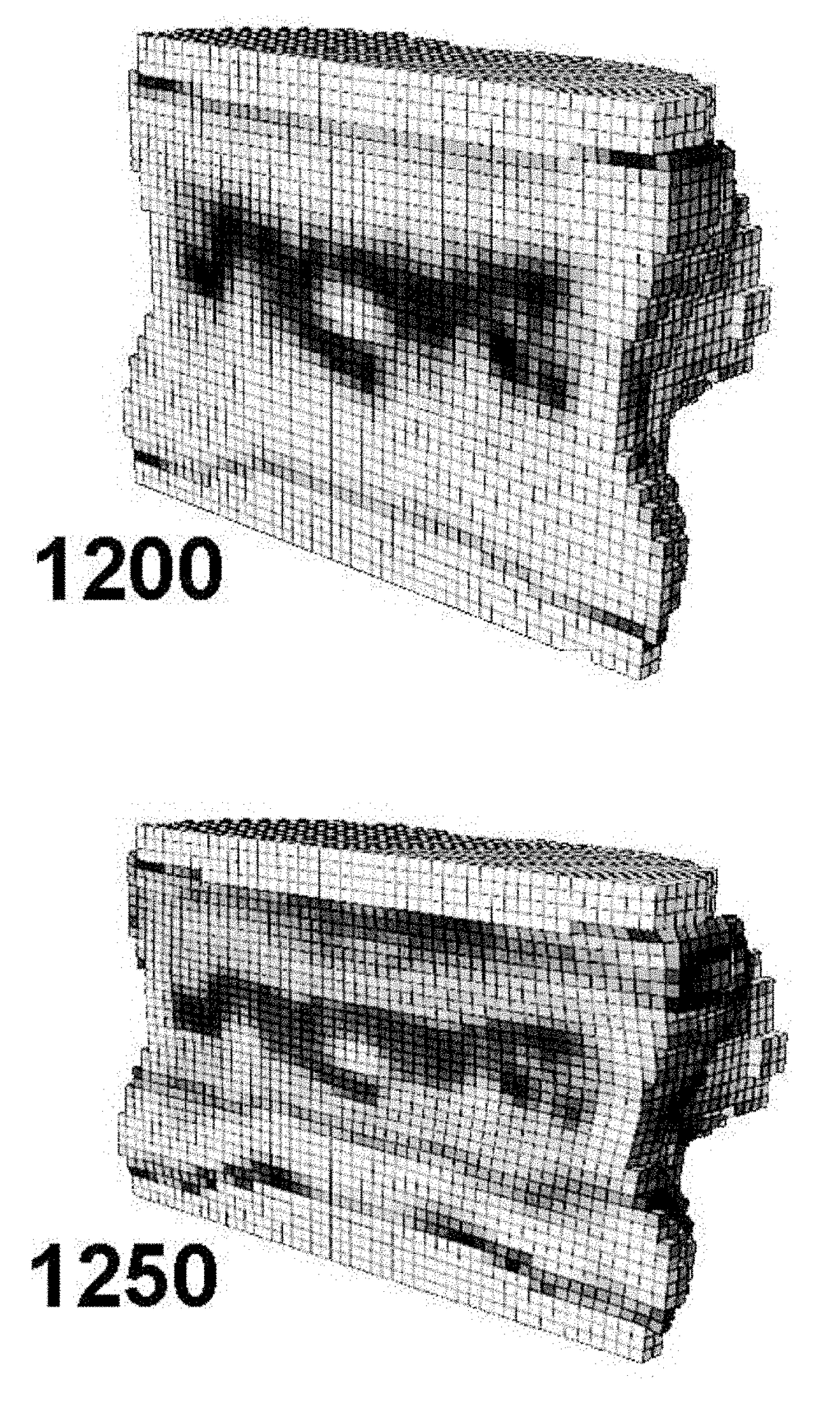
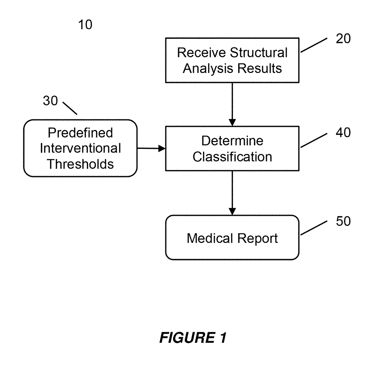
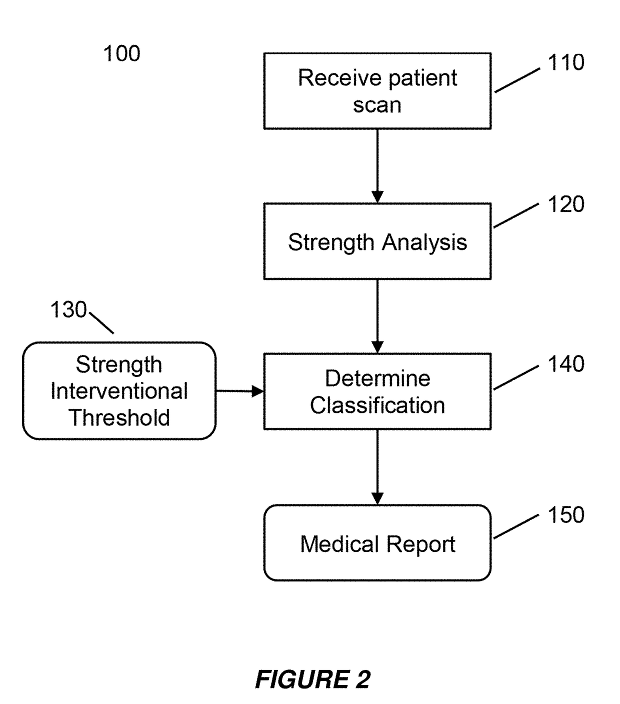
[0049]Embodiments of the present invention provide a system and method for the use of the results from a structural analysis of a patient's bone from a medical image of a patient's bone or portion thereof, as depicted in FIG. 1, to be used clinically to manage patients. The invention utilizes a comparison of a measurement from this analysis versus an interventional threshold value for fragile-bone-strength to classify a risk of fracture, allowing for more people at high risk of fracture to be identified than would be possible if only a BMD measurement were used. Some embodiments also describe medical reports that can help patients better understand their risk of fracture. The following description is presented to enable one of ordinary skill in the art to make and use the invention and is provided in the context of a patent application and its requirements.

[0050]Various modifications to the preferred embodiments and the generic principles and features described herein will be readil...


PUM


Abstract

A system and method for the use of the results from a structural analysis of a patient's bone from a clinical scan, to be used clinically to manage patients in a widespread and consistent fashion.

Description

CROSS REFERENCE TO RELATED APPLICATIONS[0001]This application is a continuation of U.S. patent application Ser. No. 14 / 455,867 filed 8 Aug. 2014 (now U.S. Pat. No. 9,848,818) which claims benefit of U.S. Patent Application No. 61 / 864,458, the contents of which are both hereby expressly incorporated in their entireties for all purposes.STATEMENT REGARDING FEDERALLY SPONSORED RESEARCH OR DEVELOPMENT[0002]This invention was made with government support under W81XWH-10-1-0896 awarded by US Army Medical Research and Materiel Command. The government has certain rights in the invention.FIELD OF THE INVENTION[0003]The present invention relates generally to diagnosis of osteoporosis and assessment of fracture risk in live patients by analysis of a medical image.BACKGROUND OF THE INVENTION[0004]The subject matter discussed in the background section should not be assumed to be prior art merely as a result of its mention in the background section. Similarly, a problem mentioned in the backgroun...

Claims


Application Information

Patent Timeline
Patent Type & Authority Applications(United States)
IPC IPC(8): A61B5/00A61B8/08A61B6/00A61B5/055A61B6/03
CPCA61B6/5211A61B8/5215A61B5/7246A61B5/4509A61B6/505A61B6/032A61B5/055A61B8/0875A61B6/463A61B6/482A61B6/5217A61B8/5223G16H50/30G16H15/00
Inventor KOPPERDAHL, DAVID L.HOFFMANN, PAUL FREDERICKLEE, DAVID CHOENHAYECK, GARRY THOMASKEAVENY, TONY M.
Owner O N DIAGNOSTICS
Why Eureka
Try Eureka