Flow meter for intravenous liquids

a flow meter and liquid technology, applied in the direction of flow monitors, liquid/fluent solid measurement, medical devices, etc., can solve the problems of unreliable orifices, high manufacturing costs, and devices that rely on the same,

Active Publication Date: 2018-05-03
WEST JONATHAN CHARLES DEVLIN
View PDF0 Cites 0 Cited by
  • Summary
  • Abstract
  • Description
  • Claims
  • Application Information

AI Technical Summary

Benefits of technology

[0022]This geometry allows the present invention to be manufactured in the same manner as existing liqu

Problems solved by technology

Devices that rely on the same principle of a liquid head being proportional to flow through an orifice have thus far been

Method used


Image

  • Flow meter for intravenous liquids
  • Flow meter for intravenous liquids
  • Flow meter for intravenous liquids

Examples


Embodiment Construction

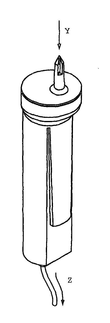
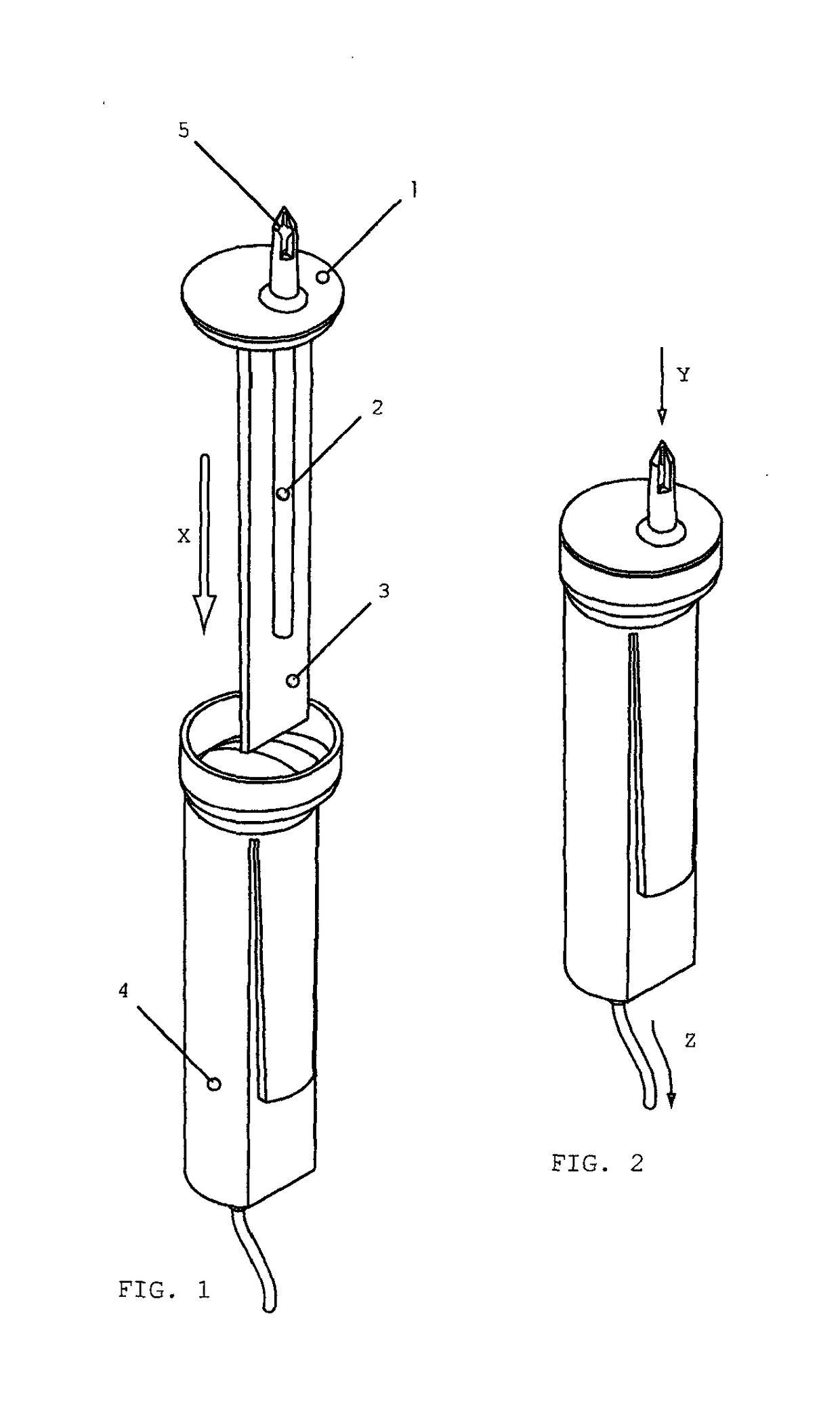
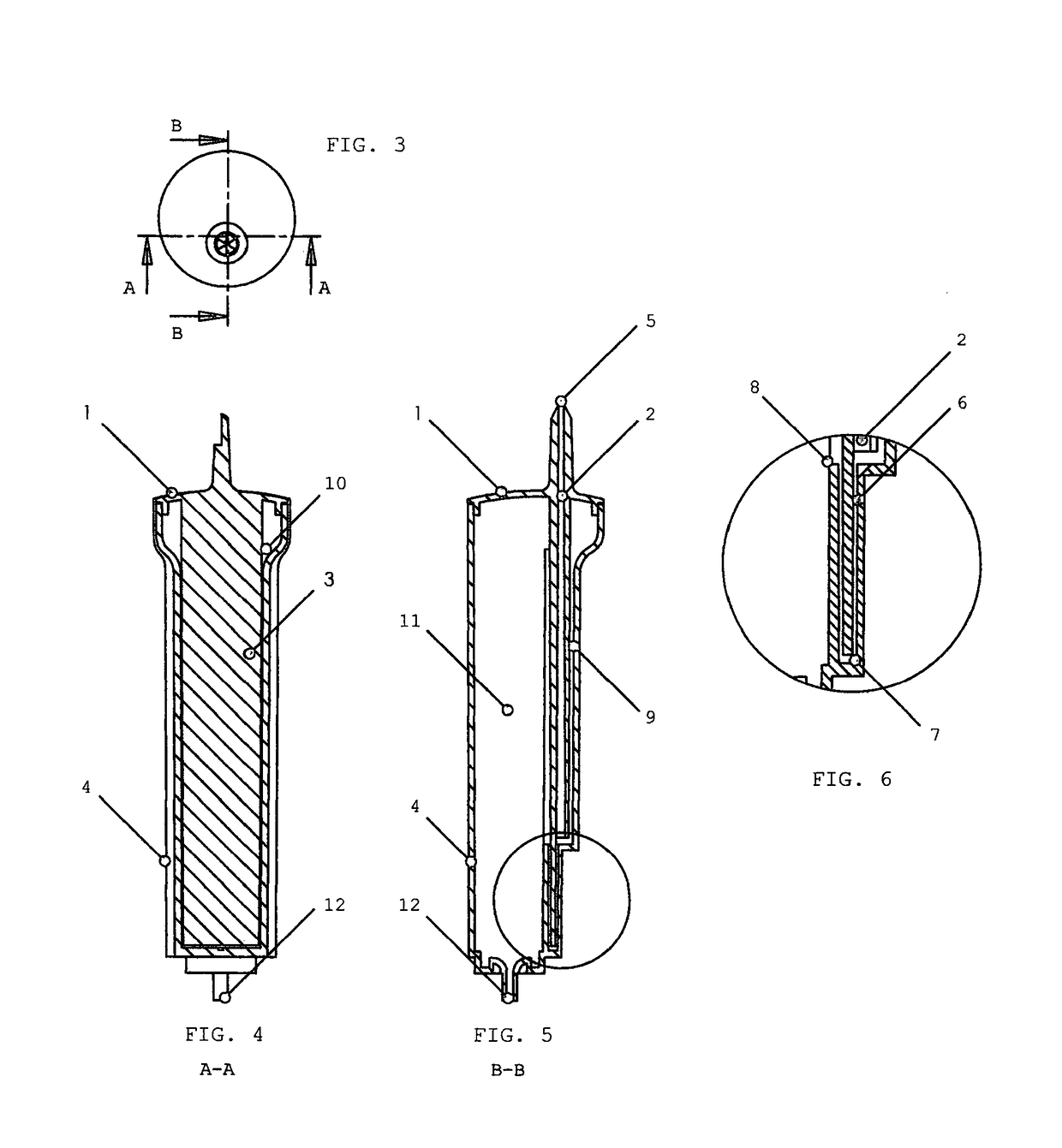
[0030]Referring to the drawings, a preferred embodiment of the present invention is illustrated in FIGS. 1 and 2. The device is assembled in manufacture by inserting (see arrow X in FIG. 1) the top (1), featuring an inlet passage (2) which may be fitted with a filter (not shown) at its lower outlet, and a dividing panel (3), into the base (4), the base being manufactured from a clear material (preferably a medical grade rigid plastic), and having a corresponding recess to accommodate the dividing panel. The finished assembly may be bonded by heat sealing, ultrasonic welding or solvent cementing. FIG. 2 shows the assembled flow meter for liquid flowing from a supply container (not shown) into the circulatory system of a patient (not shown). The liquid container is either a flexible bag or vented rigid container.

[0031]The penetrant with liquid inlet (5) is inserted into the supply container (not shown) to define an inlet passage (2) for liquid flow (see arrow Y) from the supply contai...


PUM


Abstract

A flow meter for intravenous liquids comprising a vertical inlet passage (2), a parallel indicating chamber (9), a ‘U’ shaped flow-resistant liquid passage (6), and an exit chamber (11). Liquid to be dispensed enters the inlet passage (2) via inlet (5) and moves down the passage to a junction with both the ‘U’ shaped flow-resistant passage (6), and the indicator passage. From the junction, the liquid rises up the indicator passage to a height proportional to the flow rate set by an external flow meter, and also through the flow resistant passage, which has an outlet (8) that delivers the liquid to the exit chamber (11) and from there to a patient through an outlet (12). The meter may be formed by an assembly of two injection moulded components, thus reducing manufacturing costs.

Description

FIELD OF INVENTION[0001]This invention relates generally to flow indicating devices and more particularly to improved flow meters for the administration of intravenous solutions.BACKGROUND OF THE INVENTION[0002]Intravenous administration sets are generally used to infuse various types of solutions into a patient. A set provides a means of controlling the sterile passage of a physiological liquid (e.g. saline, glucose solution etc) from a rigid or flexible supply container into a patient. Conventional intravenous administration sets feature a closed chamber with a nozzle, creating drops when the liquid flows. The purpose of this is to enable the liquid flow rate to be calculated by counting the number of drops per unit time. This can be time consuming and inaccurate, as drop size is not constant, and the conversion of drop timing to liquid flow rate can be difficult.[0003]A number of well established flow meter designs have been adapted for use in intravenous liquid administration.[0...

Claims


Application Information

Patent Timeline
IPC IPC(8): A61M5/168A61M5/165
CPCA61M5/16886A61M5/1689A61M5/165A61M2205/584A61M2205/3382G01F1/375G01F1/52
Inventor WEST, JONATHAN CHARLES DEVLIN
Owner WEST JONATHAN CHARLES DEVLIN
Why Eureka
Try Eureka