Surgical techniques for implantation of a retinal implant

a surgical technique and implant technology, applied in the field of implantable medical devices, can solve problems such as blindness, visual impairment, retinal malfunction,

Active Publication Date: 2018-05-03
NANO RETINA LTD
View PDF1 Cites 5 Cited by
  • Summary
  • Abstract
  • Description
  • Claims
  • Application Information

AI Technical Summary

Benefits of technology

[0006]For some applications, the method comprises removing a lens and a vitreous body of the eye and inserting the apparatus through a corneoscleral incision into a vitreous cavity of the subject's eye. During inserting of the apparatus, an orientation of the distal tips of the electrodes is maintained

Problems solved by technology

Retinal malfunction, due to degenerative retinal disease

Method used


Image

  • Surgical techniques for implantation of a retinal implant
  • Surgical techniques for implantation of a retinal implant
  • Surgical techniques for implantation of a retinal implant

Examples


Embodiment Construction

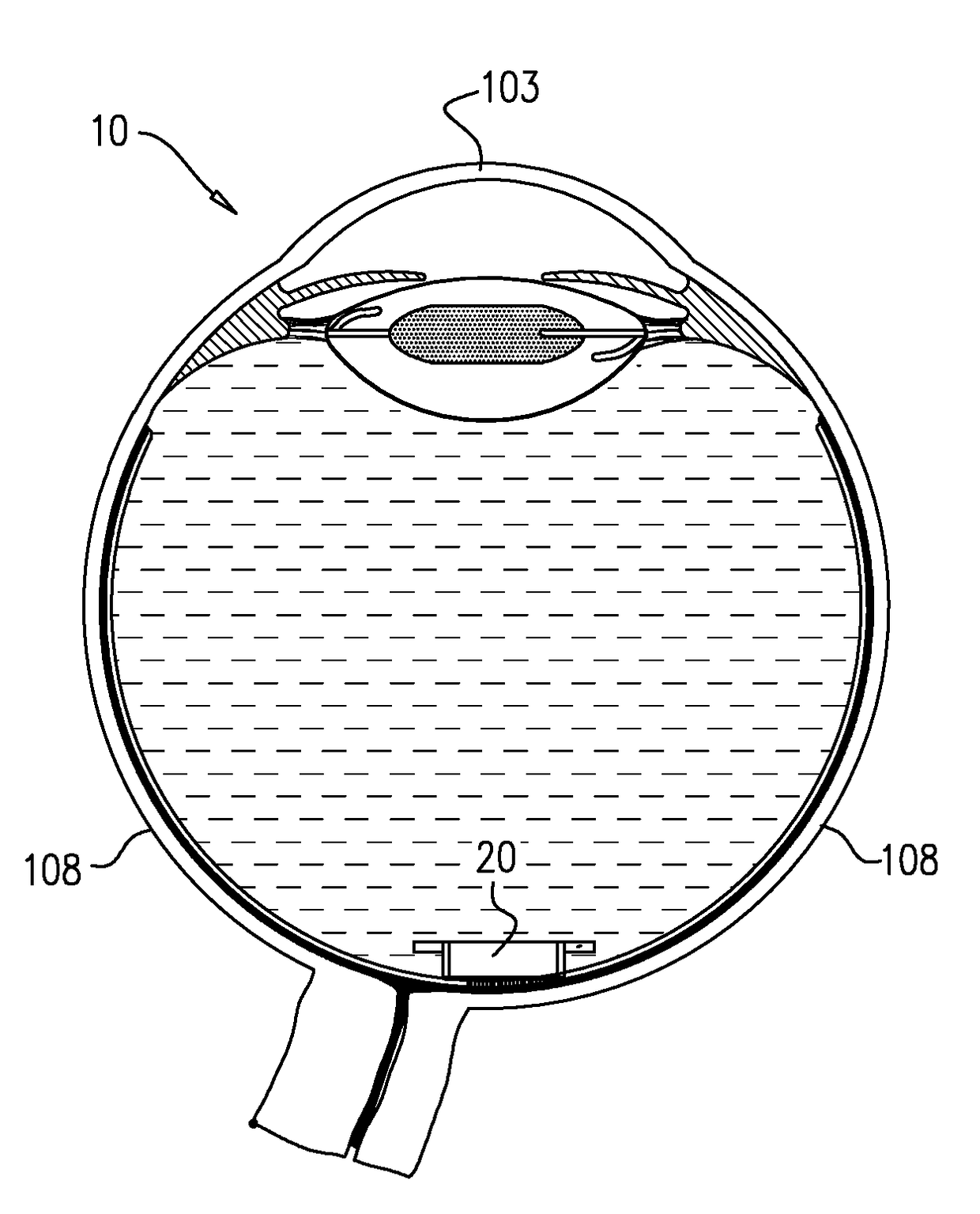
[0101]FIGS. 1-18 are schematic illustrations of the surgical procedure for implantation of apparatus 20 for stimulation of a retina 106, in accordance with some applications of the present invention. In particular, FIGS. 1-18 describe introducing apparatus 20 into eye 10 and positioning the apparatus on retina 106.

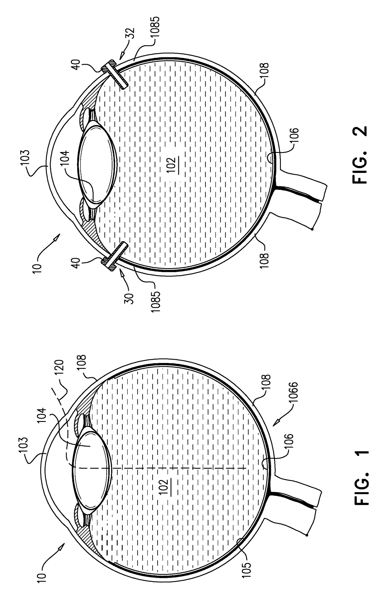
[0102]Reference is first made to FIG. 1, which is a schematic illustration of a cross section of eye 10 of the subject showing a path 120 by which apparatus 20 is to be implanted in eye 10. FIG. 1 additionally shows cornea 103, vitreous body 102, lens 104, sclera 108, choroid 105, retina 106 and macula 1066.

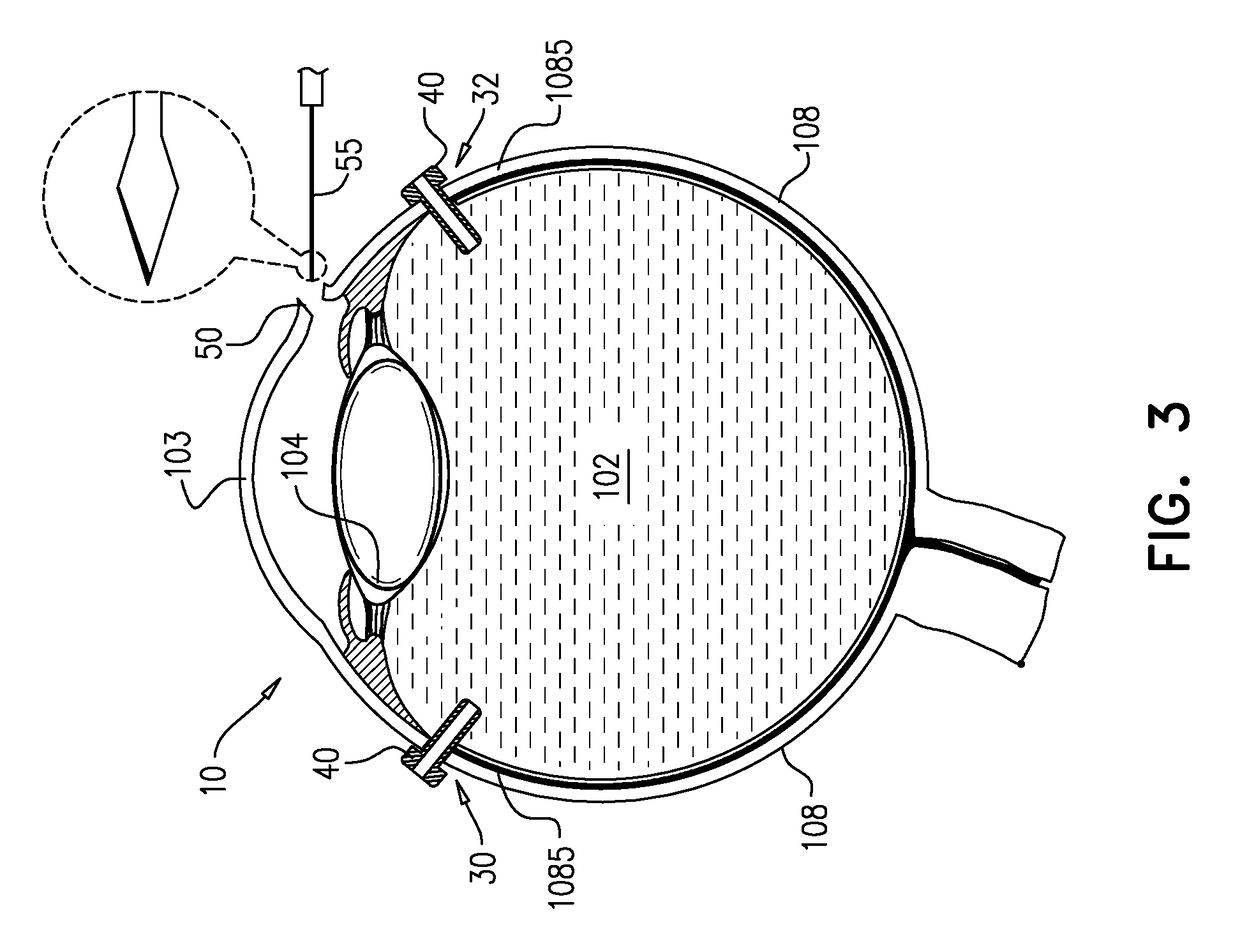
[0103]Reference is now made to FIG. 2 which is a schematic illustration of a cross section of eye 10 showing openings in a posterior-segment scleral wall 1085 of eye 10, created for insertion of one or more tools therethrough, in accordance with some applications of the present invention. For some applications, in order to facilitate the implantation procedure, at least...


PUM


Abstract

A method is provided for implanting, in an eye, apparatus having an electrode array including stimulating electrodes shaped to define distal tips protruding from the array, a plurality of photosensors, and driving circuitry, configured to drive the electrodes to apply currents to the retina. The method includes removing a lens of the eye and a vitreous body of the eye, creating a corneoscleral incision and inserting the apparatus through the corneoscleral incision into a vitreous cavity of the eye. During the inserting, an orientation of the distal tips is maintained pointing towards a cornea of the eye. Subsequently to the inserting, the apparatus is rotated such that the distal tips point towards a macula of the eye. Subsequently to the rotating, the apparatus is positioned epi-retinally, such that the distal tips of the electrodes penetrate the retina. Other applications are also described.

Description

CROSS-REFERENCE TO RELATED APPLICATIONS[0001]The present application is related to a US regular patent application to Degtiar et al., filed on even date herewith, entitled, “Retinal Implant Fixation,” which is assigned to the assignee of the present application and is incorporated herein by reference.FIELD OF THE INVENTION[0002]The present invention relates generally to implantable medical devices, and specifically to a retinal prosthesis.BACKGROUND[0003]Retinal malfunction, due to degenerative retinal diseases, is a leading cause of blindness and visual impairment. Implantation of a retinal prosthesis is a technology for restoring some useful vision in individuals suffering from retina-related blindness.[0004]The retina is a multi-layered light-sensitive structure that lines the posterior, inner part of the eye. The retina contains photoreceptor cells, rods and cones, which capture light and convert light signals into neural signals transmitted through the optic nerve to the brain....

Claims


Application Information

Patent Timeline
IPC IPC(8): A61N1/36A61F9/00A61N1/05A61N1/372
CPCA61N1/36046A61N1/37205A61N1/0543A61F9/0017
Inventor WEINBERGER, DOVRAZ PRAG, DORITMILSTAIN, YAAKOVGROSS, YOSSIMENDELEWICZ, RANIZEHAVI, MATANRIGLER, DAVID
Owner NANO RETINA LTD
Why Eureka
Try Eureka