Eureka AIR delivers breakthrough ideas for toughest innovation challenges, trusted by R&D personnel around the world.

Retinal implant fixation

a technology of implanted prosthesis and fixation, which is applied in the field of implanted medical devices, can solve the problems of retinal malfunction, blindness and visual impairment, and achieve the effect of increasing flexibility

Active Publication Date: 2018-05-03
NANO RETINA LTD
View PDF7 Cites 7 Cited by
  • Summary
  • Abstract
  • Description
  • Claims
  • Application Information

AI Technical Summary

Benefits of technology

The patent describes a design that improves the flexibility of two parts that stick out from a device or object. This is done by shaping the parts in a way that makes them more flexible than if they were straight. This design can be useful in situations where flexibility is important, such as in the design of medical devices or sports equipment.

Problems solved by technology

Retinal malfunction, due to degenerative retinal diseases, is a leading cause of blindness and visual impairment.

Method used


Image

  • Retinal implant fixation
  • Retinal implant fixation
  • Retinal implant fixation

Examples


Embodiment Construction

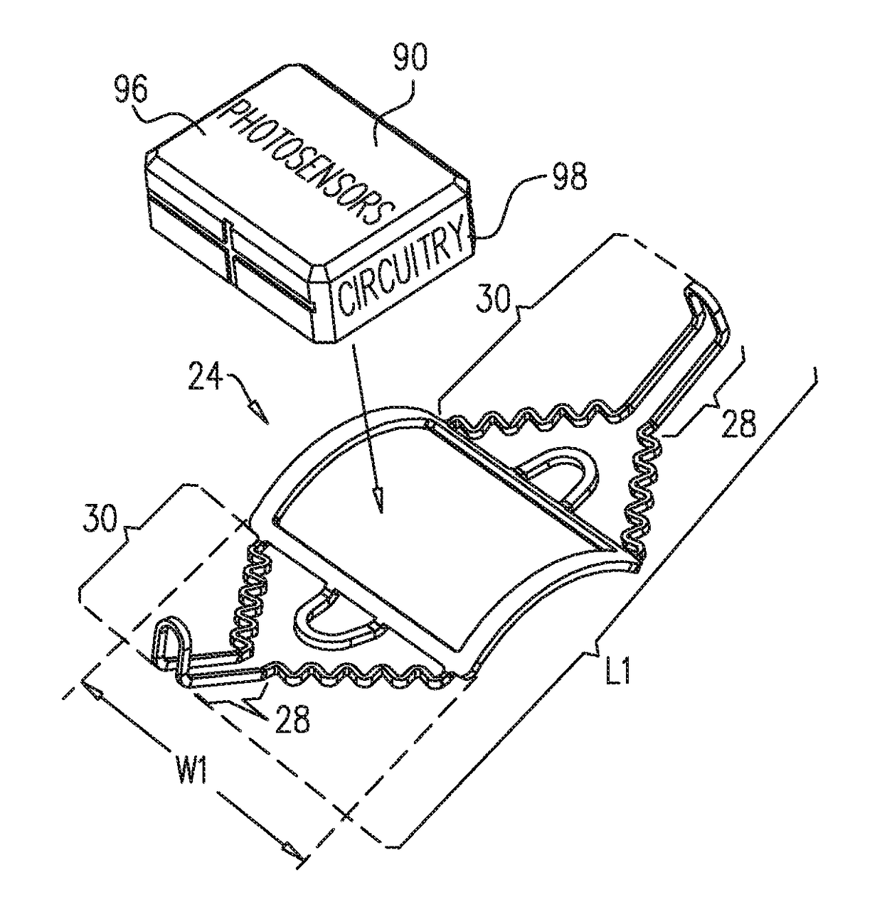
[0103]Some applications of the present invention provide apparatus and methods for securing an implantable retinal stimulator 90 to an eye of a subject. The following detailed description provides examples for such apparatus and methods for securing implantable retinal stimulator 90 in accordance with applications of the present invention.

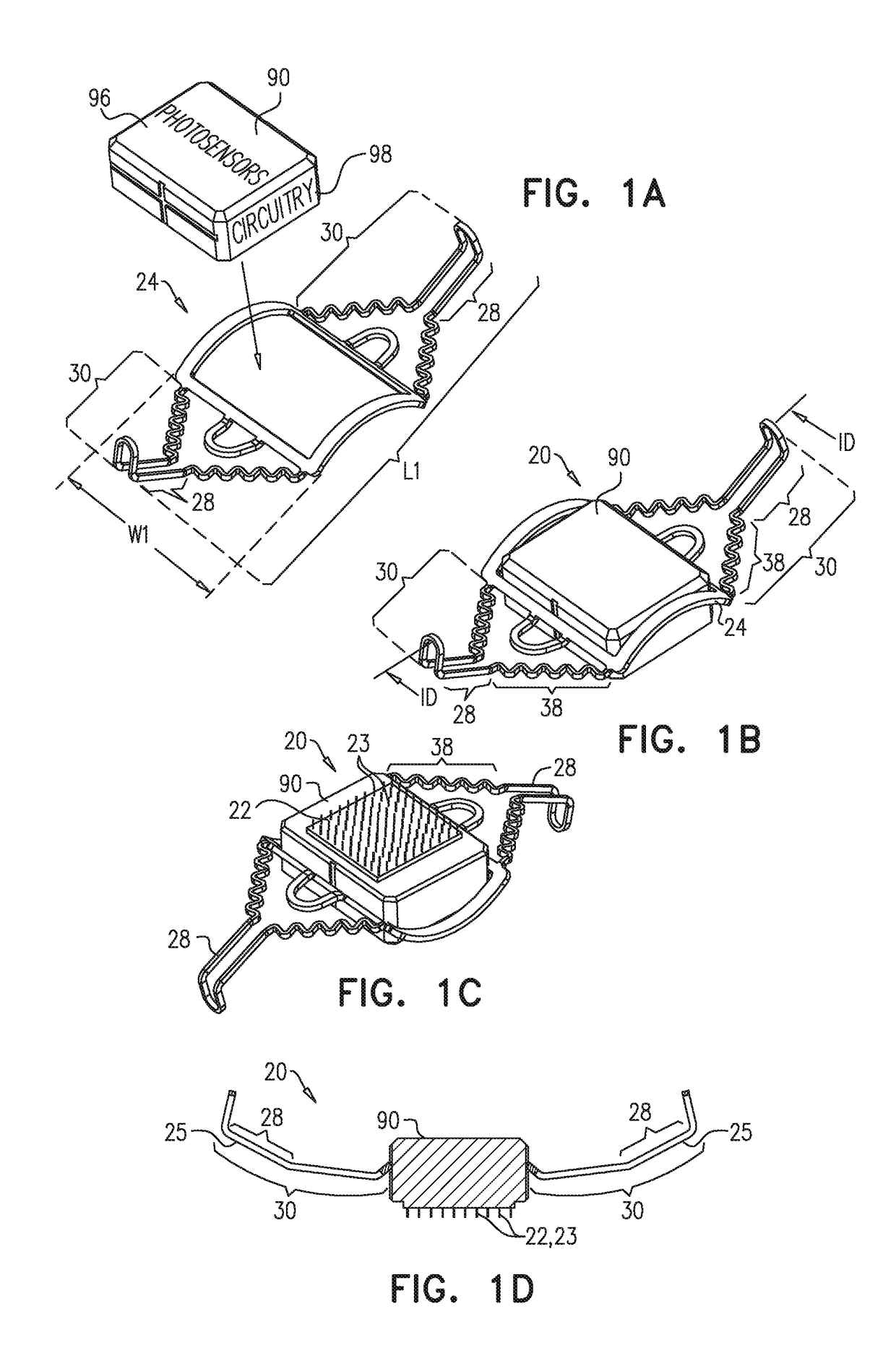
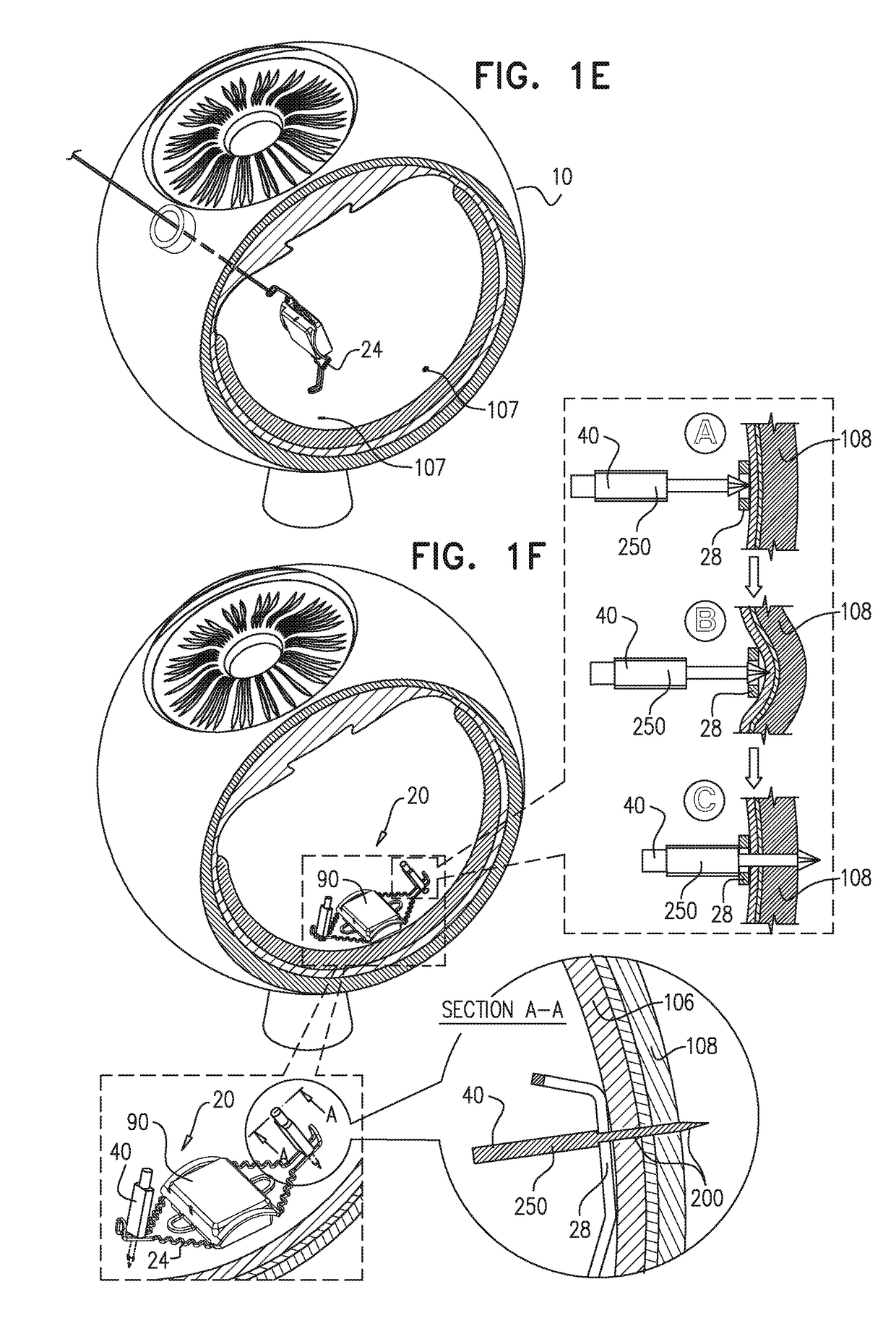
[0104]Reference is first made to FIGS. 1A-F, which are schematic illustrations of apparatus 20 for implantation in an eye of a subject, in accordance with some applications of the present invention. Apparatus 20 typically comprises implantable retinal stimulator 90 configured for implantation on a retina of a subject's eye, and frame 24 which is shaped and sized to couple to implantable retinal stimulator 90 and to surround implantable retinal stimulator 90 at least in part. Typically, frame 24 is used to fix implantable retinal stimulator 90 to the retina by means of anchoring elements that engage frame 24. Typically, having a frame 24 that is sep...


PUM


Abstract

Apparatus is provided including an implantable retinal stimulator, for implantation on a retina of an eye, and including (i) an electrode array including electrodes; (ii) a plurality of photosensors; and (iii) driving circuitry, configured to drive the electrodes to apply currents to the retina. The apparatus further includes an interface member disposed at an outer surface of the implantable retinal stimulator, e.g., a peripheral member surrounding at least a portion of the implantable retinal stimulator. The apparatus additionally includes a frame, (i) shaped and sized to couple to the peripheral member and to surround the implantable retinal stimulator at least in part, and (ii) shaped to define at least a first anchoring element receiving portion. An anchoring element is shaped and sized to be positioned in the anchoring element receiving portion and to penetrate scleral tissue of the subject. Other applications are also described.

Description

CROSS-REFERENCE TO RELATED APPLICATIONS[0001]The present application is related to a US regular patent application to Weinberger et al., filed on even date herewith, entitled, “Surgical Techniques for Implantation of a Retinal Implant,” which is assigned to the assignee of the present application and is incorporated herein by reference.FIELD OF THE INVENTION[0002]The present invention relates generally to implantable medical devices, and specifically to a retinal prosthesis.BACKGROUND[0003]Retinal malfunction, due to degenerative retinal diseases, is a leading cause of blindness and visual impairment. Implantation of a retinal prosthesis is a technology for restoring some useful vision in individuals suffering from retina-related blindness.[0004]The retina is a multi-layered light-sensitive structure that lines the posterior, inner part of the eye. The retina contains photoreceptor cells, for example rods and cones, which capture light and convert light signals into neural signals t...

Claims


Application Information

Patent Timeline
Patent Type & Authority Applications(United States)
IPC IPC(8): A61N1/36A61F9/00A61N1/05A61N1/375A61N1/372
CPCA61N1/36046A61F9/0017A61N1/37205A61N1/375A61N1/0543
Inventor DEGTIAR, BORISMENDELEWICZ, RANIMILSTAIN, YAAKOVGROSSRAZ PRAG, DORITZEHAVI, MATANRIGLER, DAVID
Owner NANO RETINA LTD
Why Eureka
Eureka Blog
Learn More