Branching structure and wire harness

a branching structure and wire harness technology, applied in the direction of insulated conductors, cables, coupling device connections, etc., can solve the problems of difficult cutting into the single line of rigid wires, lowering the reliability of connection, etc., and achieve the effect of saving the occupied space of the branching mechanism and high connection reliability

Active Publication Date: 2018-05-03
YAZAKI CORP
View PDF38 Cites 13 Cited by
  • Summary
  • Abstract
  • Description
  • Claims
  • Application Information

AI Technical Summary

Benefits of technology

[0007]The present invention is accomplished in consideration of the above-described circumstances, and an object of the present invention is to provide a branching structure and a wire harness capable of attaining high connection reliability while saving the occupied space of the branching mechanism.

Problems solved by technology

Besides, in the branching structure using a press-contacting terminal, an electrical line is pushed in between press-contacting blades to be brought into contact, and therefore, in a main line such as a power line through which a large current flows, it is apprehended that connection reliability may be lowered because the contact area is insufficient.
Press-contacting blades of a press-contacting terminal are, however, difficult to cut into the single line of the rigid wire due to the rigidity of the rigid wire, and hence, there is a demand for a branching structure replaceable with the branching structure using the branching mechanism having the press-contacting terminals.

Method used


Image

  • Branching structure and wire harness
  • Branching structure and wire harness
  • Branching structure and wire harness

Examples


first embodiment

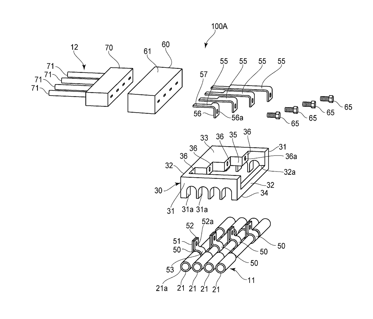
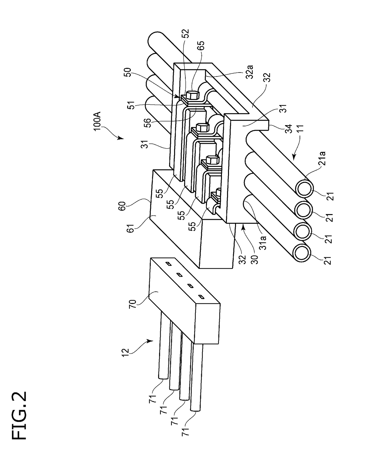
[0048]FIG. 2 is a perspective view of a branch box used in a branching structure according to a first embodiment of the present invention. FIG. 3 is an exploded perspective view of the branch box used in the branching structure of the first embodiment. FIG. 4 is a partial cross-sectional view of a connecting portion of the branch box used in the branching structure of the first embodiment.

[0049]As illustrated in FIGS. 2 and 3, the branch box 100A includes a case 30. The case 30 is made of a resin having an insulating property. The case 30 is put on a plurality of (four in the present embodiment) main lines 21 disposed in the main line harness 11. In a portion of the main line harness 11 where the case 30 is put, the cover 21a is removed from each of the main lines 21.

[0050]The case 30 is formed in the shape of a block having end surfaces 31, side surfaces 32, an upper surface 33 and a lower surface 34. The case 30 has a terminal block 35, and base surfaces 36 in the same number as t...

modification 1-1

(Modification 1-1)

[0064]FIG. 5 is a perspective view of a branch box illustrating Modification 1-1. FIG. 6 is an exploded perspective view of the branch box of Modification 1-1.

[0065]As illustrated in FIGS. 5 and 6, the main line harness 11 and the branch harness 12 are connected to each other using a branch box 100B in a branching structure of Modification 1-1.

[0066]The branch box 100B includes a case 30B and connection terminals 50B. In each of the connection terminals 50B, a bus bar 58 is integrally provided at an edge of the fixed end 51. The bus bar 58 extends along the arranging direction of the main lines 21. The bus bar 58 has, at an end thereof, a connection pin 59, and the connection pin 59 protrudes beyond the second side surface 32 of the case 30B. The respective bus bars 58 are formed to have different lengths so that the lengths of the connection pins 59 protruding beyond the side surface 32 can be equivalent. The connection pins 59 of these bus bars 58 are inserted in...

second embodiment

[0071]Next, a second embodiment of the present invention will be described. It is noted that like reference signs are used to refer to like elements used in the first embodiment described above to omit the description.

[0072]FIG. 7 is a perspective view of a branch box used in a branching structure of the second embodiment. FIG. 8 is a cross-sectional view, taken along a routing direction of main lines, of the branch box used in the branching structure of the second embodiment. FIG. 9 is a partially cross-sectional perspective view of the branch box used in the branching structure of the second embodiment. FIG. 10 is a plan view of the branch box used in the branching structure of the second embodiment with a cover thereof removed. FIG. 11 is a perspective view of a main line harness connected using the branching structure of the second embodiment.

[0073]As illustrated in FIGS. 7 to 10, the main line harness 11 and the branch harness 12 are connected to each other using a branch box 2...


PUM

PropertyMeasurementUnit
current capacityaaaaaaaaaa
poweraaaaaaaaaa
distanceaaaaaaaaaa

Abstract

A branching structure for connecting a branch harness to a main line harness, includes connection terminals configured to electrically connect branch lines of the branch harness to main lines of the main line harness respectively, a terminal block on which the connection terminals are supported, and fasteners that respectively fasten the connection terminals onto the terminal block. Each of the connection terminals has a belt-shaped wound portion to be wound around a corresponding one of the main lines. The wound portion is fastened by a corresponding one of the fasteners so that both ends of the wound portion come closer to each other and a center portion of the wound portion tightens around the main line so as to be brought into surface contact with a bar conductor of the main line.

Description

CROSS REFERENCE TO RELATED APPLICATIONS[0001]This application is based on Japanese Patent Application (No. 2016-210511) filed on Oct. 27, 2016, the contents of which are incorporated herein by reference.BACKGROUND OF THE INVENTION1. Field of the Invention[0002]The present invention relates to a branching structure and a wire harness.2. Description of the Related Art[0003]For example, in a vehicle wire harness, a main line harness into which main lines such as a power line and a grounding line are collected is connected to branch harnesses to be connected to respective electrical components. As a technique to branch a main line harness by connection of a branch harness, there is a technique in which a branching mechanism having press-contacting terminals is used to connect a main line of a main line harness to a branch line by establishing a press-contacting connection between the press-contacting terminals of the branching mechanism and the main line (see, for example, JP-A-2015-227...

Claims


Application Information

Patent Timeline
Patent Type & Authority Applications(United States)
IPC IPC(8): B60R16/02B60R16/023B60R16/03H01R13/66H01B7/00
CPCB60R16/0215B60R16/023B60R16/03H01R13/6691H01B7/0045H02G3/0481B60R16/0222H02G3/06H01R4/34H01R4/363H01R4/38H01R4/56H01R9/2408H01R2107/00H02G3/16H02G3/32H01R2201/26
Inventor TSUKAMOTO, MASASHIKAMBARA, SHINGOSANO, YOSHIHIKOHARA, MOTOKOOKAWA, TAKASHISHIMIZU, MAISAITOU, SATOSHITAKAGI, AKIHIROICHIKAWA, MASAHIRO
Owner YAZAKI CORP
Why Eureka
Try Eureka