
Wellbore System With Lateral Wells

a wellbore system and lateral well technology, applied in the field of wells, can solve the problems of early water breakthrough, limited reservoir productivity,

Inactive Publication Date: 2018-05-03
SAUDI ARABIAN OIL CO
View PDF12 Cites 17 Cited by
  • Summary
  • Abstract
  • Description
  • Claims
  • Application Information

AI Technical Summary

Benefits of technology

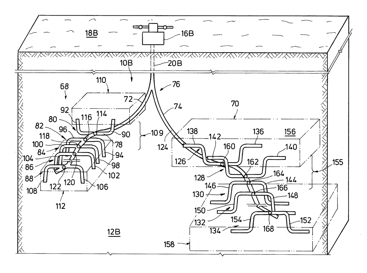
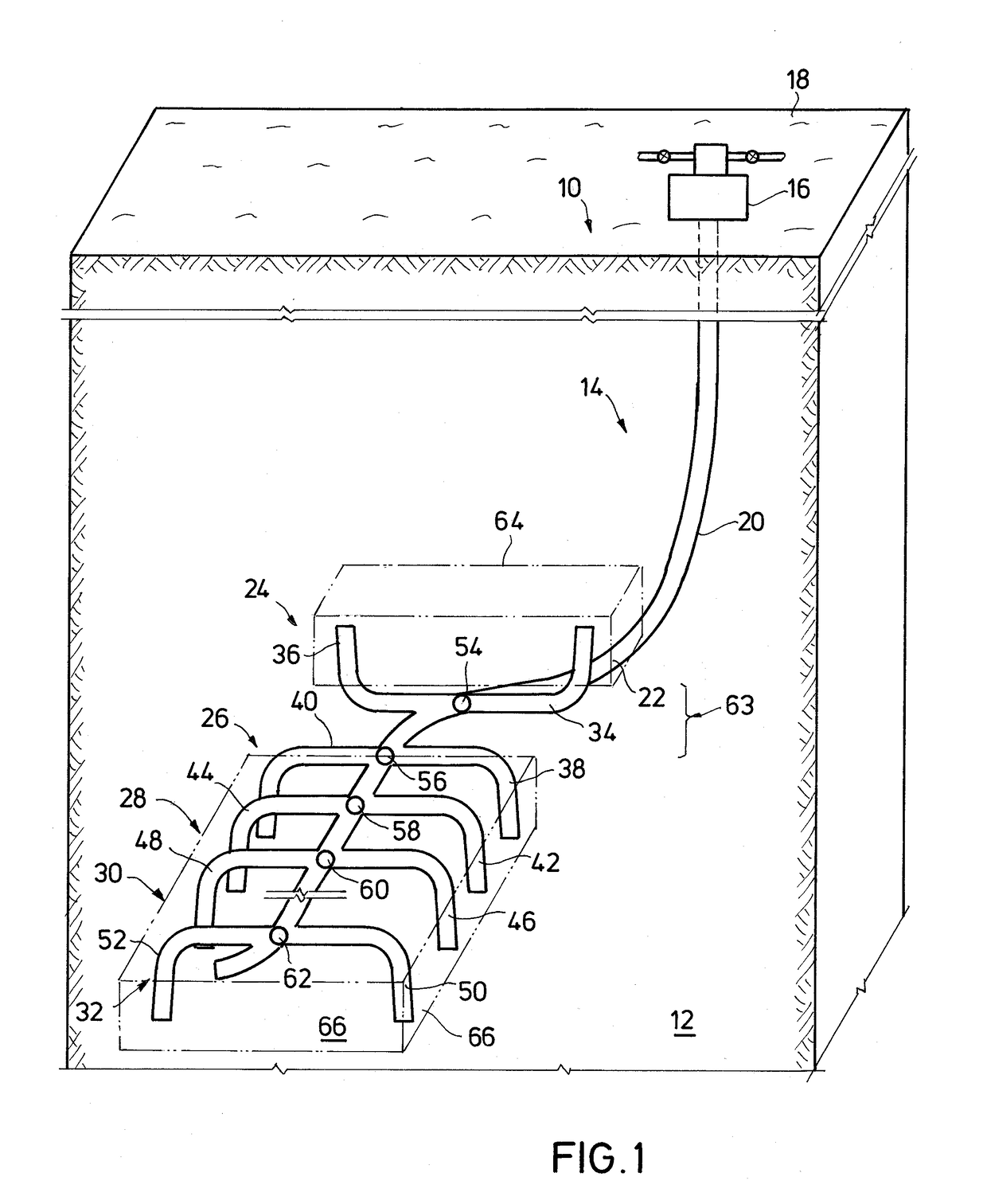
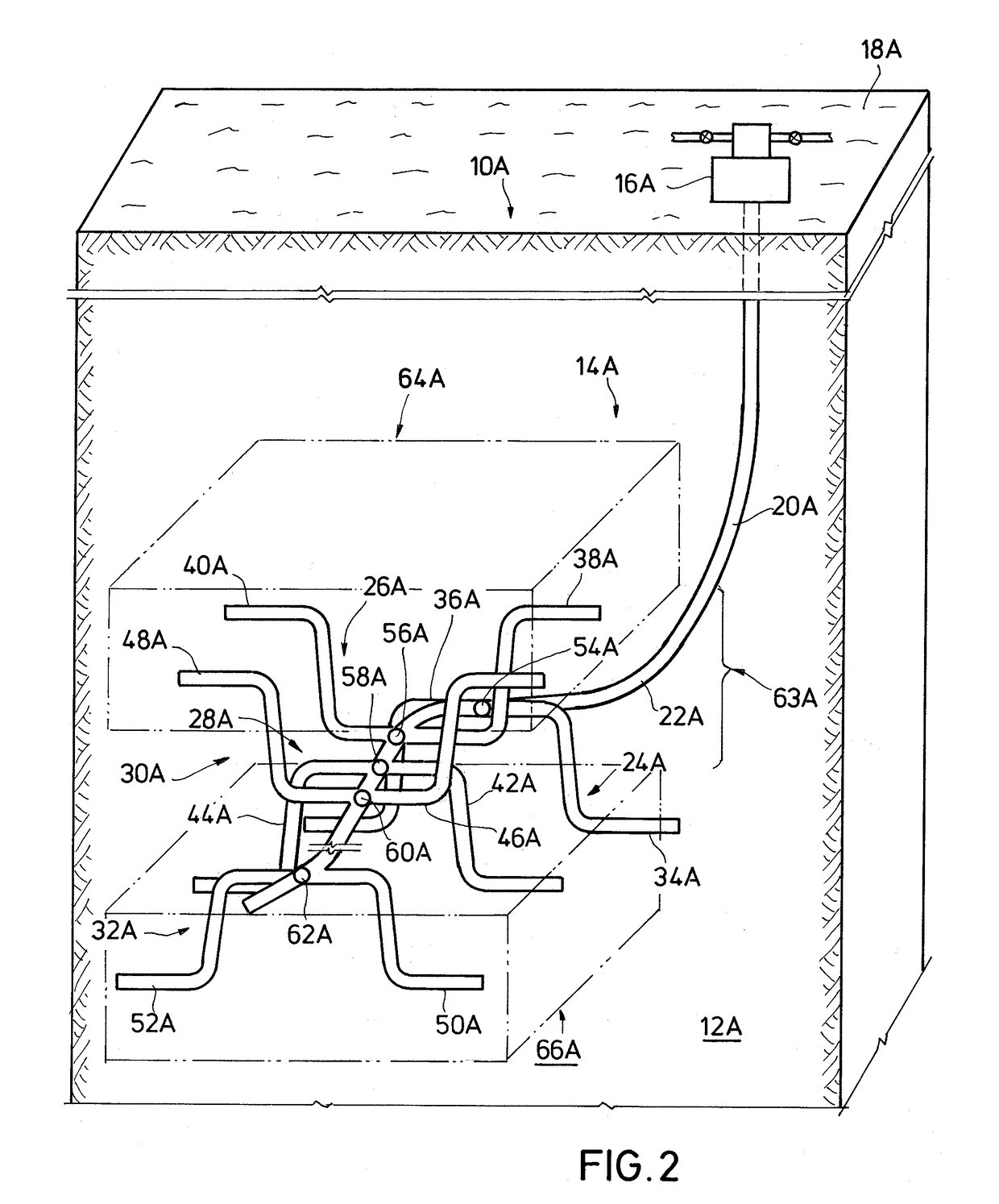
The patent describes a wellbore system that includes a motherbore and two lateral wellbores that extend into different producing zones in a subterranean formation. The system also includes inflow control valves to regulate the flow of fluid from the lateral wellbores into the motherbore. The lateral wellbore can have a vertical portion that penetrates both the shallower and deeper producing zones. The system can also include a primary wellbore and a wellhead assembly on surface that is connected to the motherbore. The patent also describes a method for operating the wellbore system by directing fluid flows into the non-producing zone and controlling the flow rates of each fluid. The method can also involve forming a motherbore and lateral bores in the non-producing and producing zones, respectively. The patent also mentions monitoring the composition of the fluid flows and blocking the fluid from entering certain zones based on the presence of certain constituents. The technical effects of the patent include improved wellbore system design and improved methods for fluid control and monitoring.

Problems solved by technology

Lateral wellbores formed by current drilling methods and systems often intersect these fractures.
For example, while non-deviated wells can avoid fractures and early water breakthrough, their productivity is very limited in tight reservoirs.
A shortcoming with horizontal wells is that although they can enhance well productivity, horizontal wells are more prone to intersect fractures, which may cause early water breakthrough.

Method used


Image

  • Wellbore System With Lateral Wells
  • Wellbore System With Lateral Wells
  • Wellbore System With Lateral Wells

Examples


Embodiment Construction

[0017]The method and system of the present disclosure will now be described more fully hereinafter with reference to the accompanying drawings in which embodiments are shown. The method and system of the present disclosure may be in many different forms and should not be construed as limited to the illustrated embodiments set forth herein; rather, these embodiments are provided so that this disclosure will be thorough and complete, and will fully convey its scope to those skilled in the art. Like numbers refer to like elements throughout. In an embodiment, usage of the term “about” includes + / −5% of the cited magnitude. In an embodiment, usage of the term “substantially” includes + / −5% of the cited magnitude.

[0018]It is to be further understood that the scope of the present disclosure is not limited to the exact details of construction, operation, exact materials, or embodiments shown and described, as modifications and equivalents will be apparent to one skilled in the art. In the ...


PUM


Abstract

A well system that intersects a subterranean formation, and which includes a motherbore disposed in a non-producing formation that is between producing zones. Connate fluids in the formation can be produced with the well system; alternatively, fluids can be injected into the formation through the well system. Lateral wellbores extend from the motherbore to depths that are both deeper and shallower than the motherbore. Flow to / from each lateral wellbore can be controlled by an inflow control valve. Wellhead assemblies mounted over an opening of the well system can be at a location that is spaced away from a populated area and far away from the hydrocarbon formation.

Description

BACKGROUND OF THE INVENTION1. Field of Invention[0001]The present disclosure relates to producing hydrocarbons from a subterranean formation. More specifically, the present disclosure relates to producing hydrocarbons from separate zones that are at different depths.2. Description of Prior Art[0002]Hydrocarbon producing wellbores extend below the Earth's surface where they intersect subterranean formations in which hydrocarbons are trapped. The wellbores generally are created with drilling systems that include drill bits mounted on an end of a drill string, and a drive system above the opening to the wellbore that rotates the drill string and bit. Cutting elements on the drill bit scrape or otherwise impact the bottom of the wellbore as the bit is rotated and excavate material from the formation thereby deepening the wellbore. Drilling fluid is typically pumped down the drill string and discharged from the drill bit into the wellbore. The drilling fluid flows back up the wellbore in...

Claims


Application Information

Patent Timeline
Patent Type & Authority Applications(United States)
IPC IPC(8): E21B43/30E21B49/08E21B41/00
CPCE21B43/305E21B34/06E21B41/0035E21B49/08E21B43/14
Inventor ALHUTHALI, AHMEDALALYAN, ESSAM
Owner SAUDI ARABIAN OIL CO
Learn More