
Neutron Imager With Spaced Diamond Detector Arrays

a diamond detector array and neutron imager technology, applied in the field of neutron detection and imaging, can solve the problems of unsuitable space missions, small unmanned aircraft, hand-held devices, bulky and power-consuming previous neutron imagers that have used proportional counters or scintillators connected to photomultiplier tubes, etc., and achieve the effect of high electron/hole mobility

Active Publication Date: 2018-05-03
SOUTHWEST RES INST
View PDF0 Cites 5 Cited by
  • Summary
  • Abstract
  • Description
  • Claims
  • Application Information

AI Technical Summary

Benefits of technology

The patent is about a neutron detection system that uses diamond detectors and special logic to image neutrons. These detectors are tolerant to extreme temperatures, making them suitable for use in space missions. The system can determine the composition of volatile components in remote areas like the Moon or small bodies with high resolution. The invention can support lander or rover-based missions for primitive bodies and the Moon. Overall, this system provides valuable information for future planetary resource utilization and human exploration.

Problems solved by technology

However, previous neutron imagers that have used proportional counters or scintillators connected to photomultiplier tubes are bulky and power-consuming.
These characteristics make these systems unsuitable for space missions, small unmanned aircraft, and hand-held devices.
In addition, these systems are highly sensitive to many types of radiations, making them unsuitable for use in environments with high background radiation levels.

Method used


Image

  • Neutron Imager With Spaced Diamond Detector Arrays
  • Neutron Imager With Spaced Diamond Detector Arrays
  • Neutron Imager With Spaced Diamond Detector Arrays

Examples


Embodiment Construction

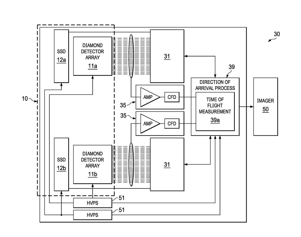
[0019]The following description is directed to neutron detection, based on epithermal and fast neutron elastic scatterings. As explained below, the neutron detector uses two spaced diamond detector arrays as the scattering media and sensors. The neutron detection system measures both carbon recoil energies and neutron arrival timings to determine the arrival direction of neutrons. From this data, images representing neutron events can be constructed.

[0020]Overview of Detector

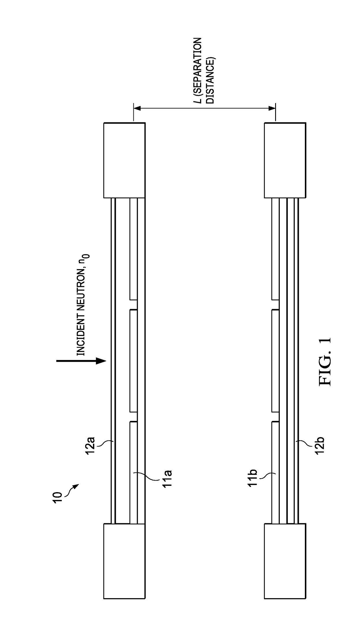
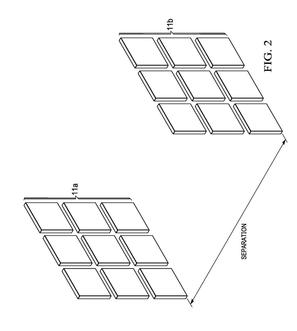
[0021]FIG. 1 is a side view, and FIG. 2 is a perspective view, of the neutron detector 10. Detector 10 is a “two-stage” detector, having a pair of diamond detector layers 11a and 11b. Each diamond detector layer 11a and 11b has an associated thin silicon layer 12a and 12b, respectively.

[0022]Each diamond detector layer 11a and 11b is an array of single-crystal diamond detectors. An example of a suitable diamond detector array for layer 11a or 11b is a three-by-three array, with a total of nine pieces. A typical ...


PUM


Abstract

A neutron detector system, with a detector having a pair of spaced diamond detector layers, sandwiched between outer silicon layers. In response to incident neutrons, the detector system measures pulse heights and response times, and from those measurements, calculates the carbon recoil energy and time of flight of scattered neutrons. This data is further used to calculate a “direction cone”, which represents the approximate angle of arrival of the incident neutron. These direction cones can be used to image neutron events.

Description

TECHNICAL FIELD OF THE INVENTION[0001]This invention relates to neutron detection and imaging, and more particularly to a neutron imager using diamond detector arrays.CROSS-REFERENCE TO RELATED APPLICATION[0002]This application claims the benefit of U.S. Provisional Application No. 62 / 416,116, filed Nov. 1, 2016.BACKGROUND OF THE INVENTION[0003]Neutron detection is the effective detection of neutrons entering a detector instrument that receives and measures an incoming neutron flux. Two key aspects to effective neutron detection are its hardware and software. Detection hardware refers to the kind of neutron detector used and the electronics used for detection. Detection software consists of analysis tools that perform analysis tasks to measure the number and energies of neutrons striking the detector.[0004]One approach to neutron imaging uses scintillator arrays, which rely on neutrons' elastic scattering properties with protons. Neutrons collide with the nucleus of atoms in the sci...

Claims


Application Information

Patent Timeline
Patent Type & Authority Applications(United States)
IPC IPC(8): G01T3/00
CPCG01T3/003G01T3/005G01T1/26G01T3/08
Inventor OGASAWARA, KEIICHI
Owner SOUTHWEST RES INST
Learn More