Optical image capturing system
a technology of optical image and optical system, applied in the field of compact can solve the problems of poor imaging quality at peripheral parts, increased difficulty in manufacturing such an optical system, and optical system with a wide view angle usually has higher distortion during imaging, so as to improve the total pixels contained in an image and improve the imaging quality for image formation. , the effect of widening the view angle of the optical image capturing system
- Summary
- Abstract
- Description
- Claims
- Application Information
AI Technical Summary
Benefits of technology
Problems solved by technology
Method used
Image

Examples
first embodiment
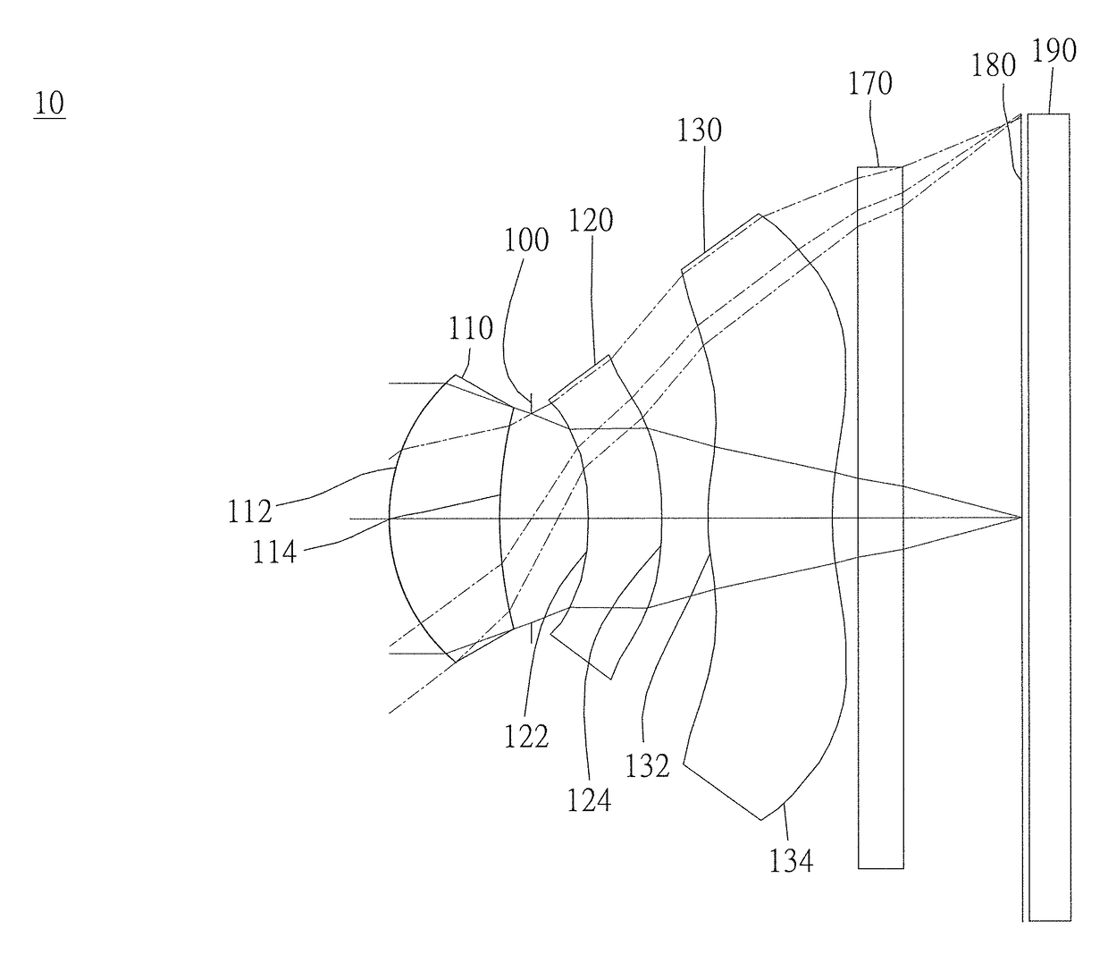
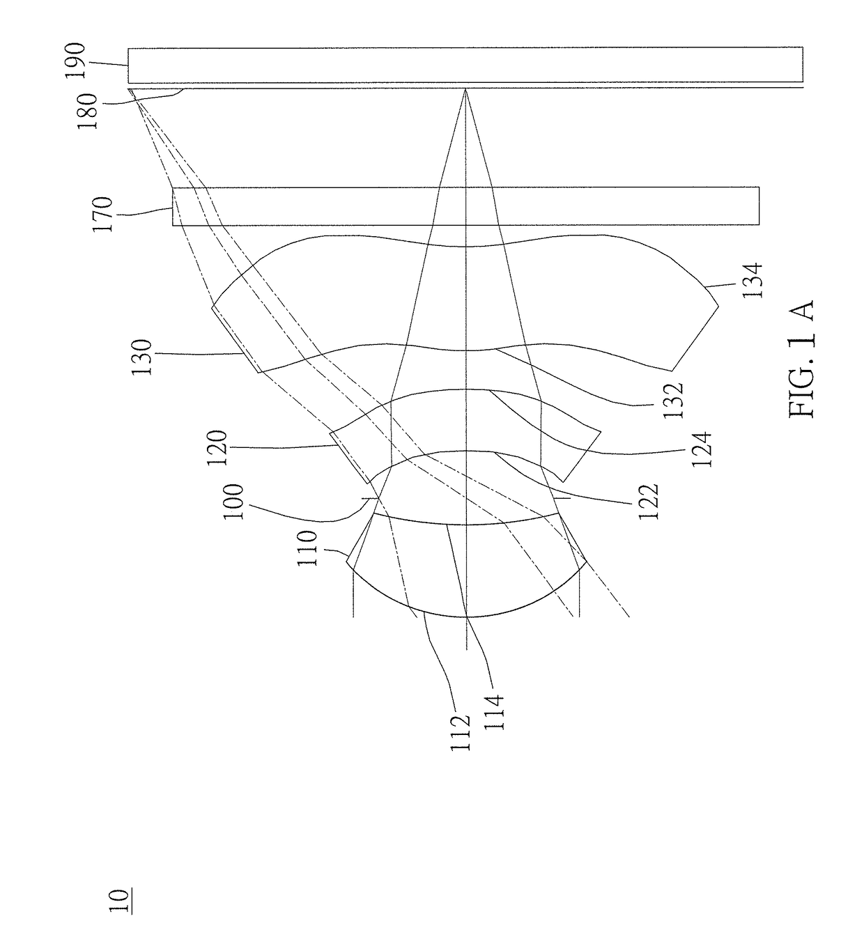
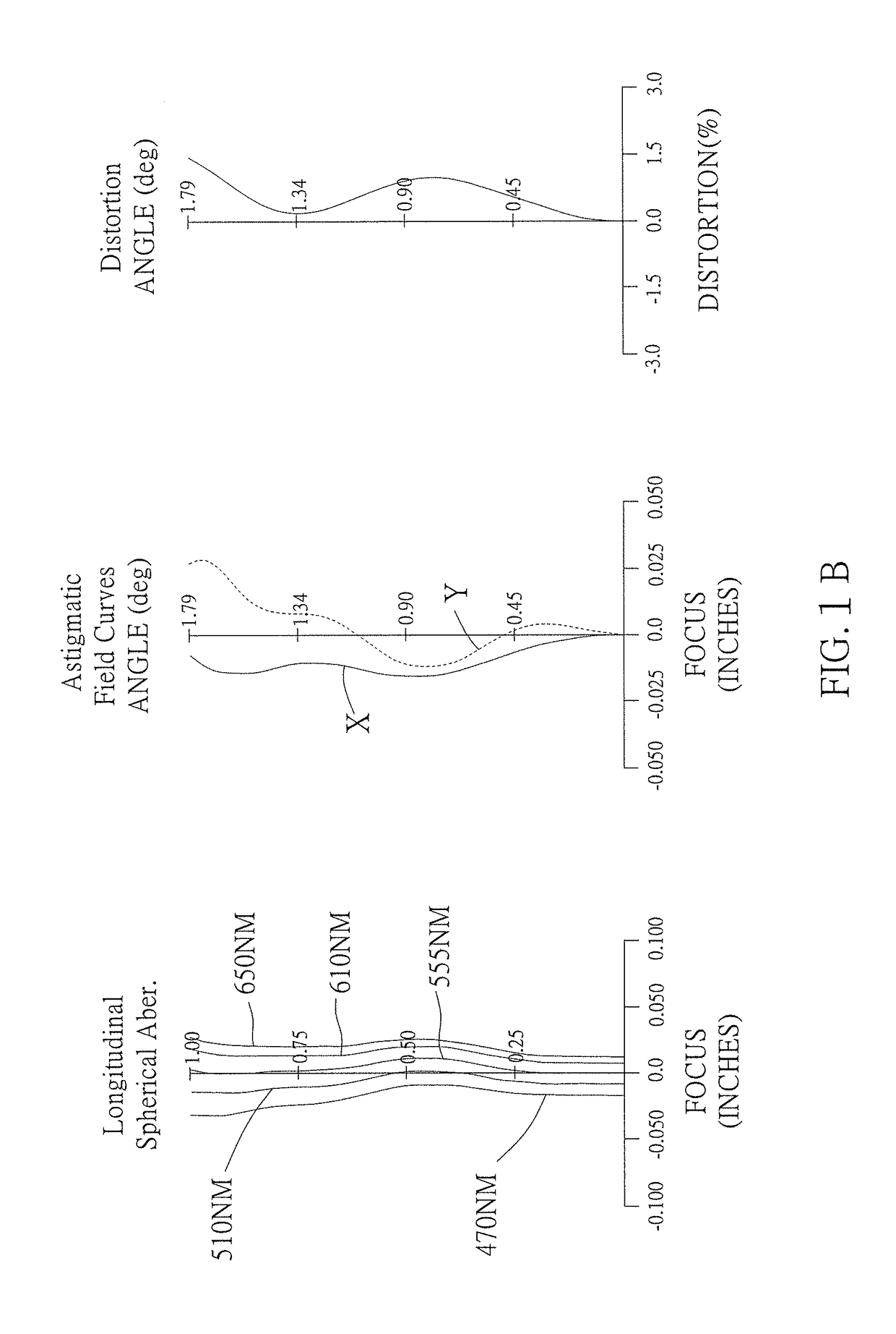
[0104]As shown in FIG. 1A and FIG. 1B, an optical image capturing system 10 of the first embodiment of the present invention includes, along an optical axis from an object side to an image side, a first lens 110, an aperture 100, a second lens 120, a third lens 130, an infrared rays filter 170, an image plane 180, and an image sensor 190. FIG. 1C shows a tangential fan and a sagittal fan of the optical image capturing system 10 of the first embodiment of the present application, and a transverse aberration diagram at 0.7 field of view when a longest operation wavelength and a shortest operation wavelength pass through an edge of the aperture 100.
[0105]The first lens 110 has positive refractive power and is made of plastic. An object-side surface 112 thereof, which faces the object side, is a convex aspheric surface, and an image-side surface 114 thereof, which faces the image side, is a concave aspheric surface. A profile curve length of the maximum effective half diameter of an obj...
second embodiment
[0138]As shown in FIG. 2A and FIG. 2B, an optical image capturing system 20 of the second embodiment of the present invention includes, along an optical axis from an object side to an image side, an aperture 200, a first lens 210, a second lens 220, a third lens 230, an infrared rays filter 270, an image plane 280, and an image sensor 290. FIG. 2C is a transverse aberration diagram at 0.7 field of view of the second embodiment of the present application.
[0139]The first lens 210 has positive refractive power and is made of plastic. An object-side surface 212 thereof, which faces the object side, is a convex aspheric surface, and an image-side surface 214 thereof, which faces the image side, is a concave aspheric surface. The object-side surface 212 and the image-side surface 214 both have an inflection point.
[0140]The second lens 220 has positive refractive power and is made of plastic. An object-side surface 222 thereof, which faces the object side, is a concave aspheric surface, an...
third embodiment
[0148]As shown in FIG. 3A and FIG. 3B, an optical image capturing system of the third embodiment of the present invention includes, along an optical axis from an object side to an image side, an aperture 300, a first lens 310, a second lens 320, a third lens 330, an infrared rays filter 370, an image plane 380, and an image sensor 390. FIG. 3C is a transverse aberration diagram at 0.7 field of view of the third embodiment of the present application.
[0149]The first lens 310 has positive refractive power and is made of plastic. An object-side surface 312 thereof, which faces the object side, is a convex aspheric surface, and an image-side surface 314 thereof, which faces the image side, is a concave aspheric surface. The object-side surface 312 and the image-side surface 314 both have an inflection point.
[0150]The second lens 320 has positive refractive power and is made of plastic. An object-side surface 322 thereof, which faces the object side, is a convex aspheric surface, and an i...
PUM
 Abstract
Description
Claims
Application Information
 - Generate Ideas
- Intellectual Property
- Life Sciences
- Materials
- Tech Scout
- Unparalleled Data Quality
- Higher Quality Content
- 60% Fewer Hallucinations
Browse by: Latest US Patents, China's latest patents, Technical Efficacy Thesaurus, Application Domain, Technology Topic, Popular Technical Reports.
© 2025 PatSnap. All rights reserved.Legal|Privacy policy|Modern Slavery Act Transparency Statement|Sitemap|About US| Contact US: help@patsnap.com