
Method and module for processing high dynamic range (HDR) image and display device using the same

a high dynamic range and image technology, applied in image enhancement, television systems, instruments, etc., can solve the problem of not applying just-noticeable differences (jnd) in bright rooms, and achieve the effects of reducing luminance saturation, improving visibility and image quality, and increasing gray-level distinguishability of hdr images

Active Publication Date: 2018-05-03
LG DISPLAY CO LTD
View PDF11 Cites 5 Cited by
  • Summary
  • Abstract
  • Description
  • Claims
  • Application Information

AI Technical Summary

Benefits of technology

The present invention provides a method and module for processing an HDR image, which can adjust the luminance of the image based on illuminance to improve visibility. If the high-luminance rate of the adjusted image is equal to or greater than a threshold, the luminance of the high-luminance part of the image is increased to reduce luminance saturation and enhance gray-level distinguishability, improving visibility and image quality. The display device according to the invention displays the HDR image with luminance equal to or less than the target peak luminance of the display device if the high-luminance rate of the image is less than the threshold, improving visibility and maintaining power consumption.

Problems solved by technology

However, since the PQ-EOTF used in the image processing procedure of the display device is derived in a dark room, a just-noticeable difference (JND) in a bright room is not applied.

Method used


Image

  • Method and module for processing high dynamic range (HDR) image and display device using the same
  • Method and module for processing high dynamic range (HDR) image and display device using the same
  • Method and module for processing high dynamic range (HDR) image and display device using the same

Examples


Embodiment Construction

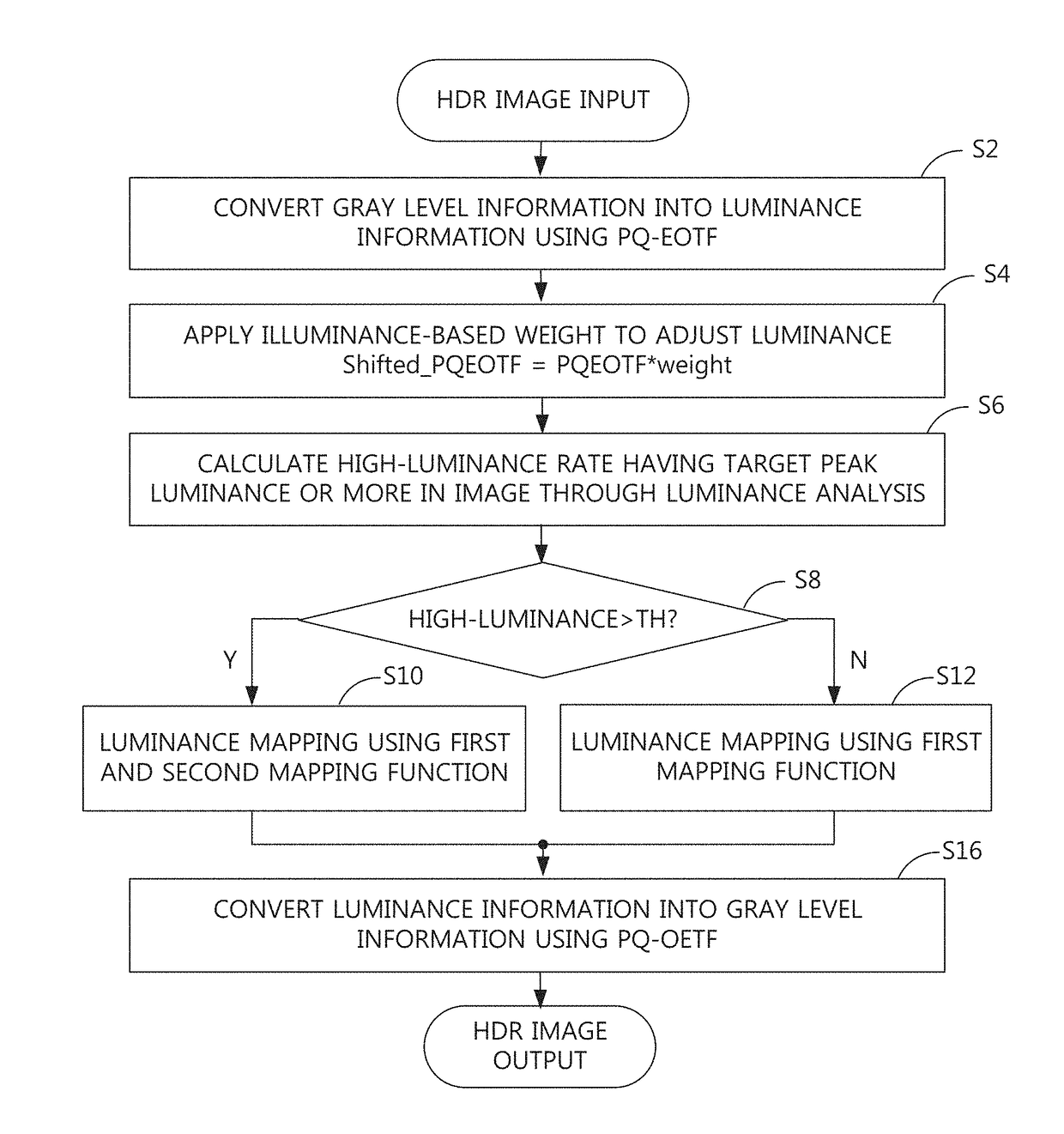
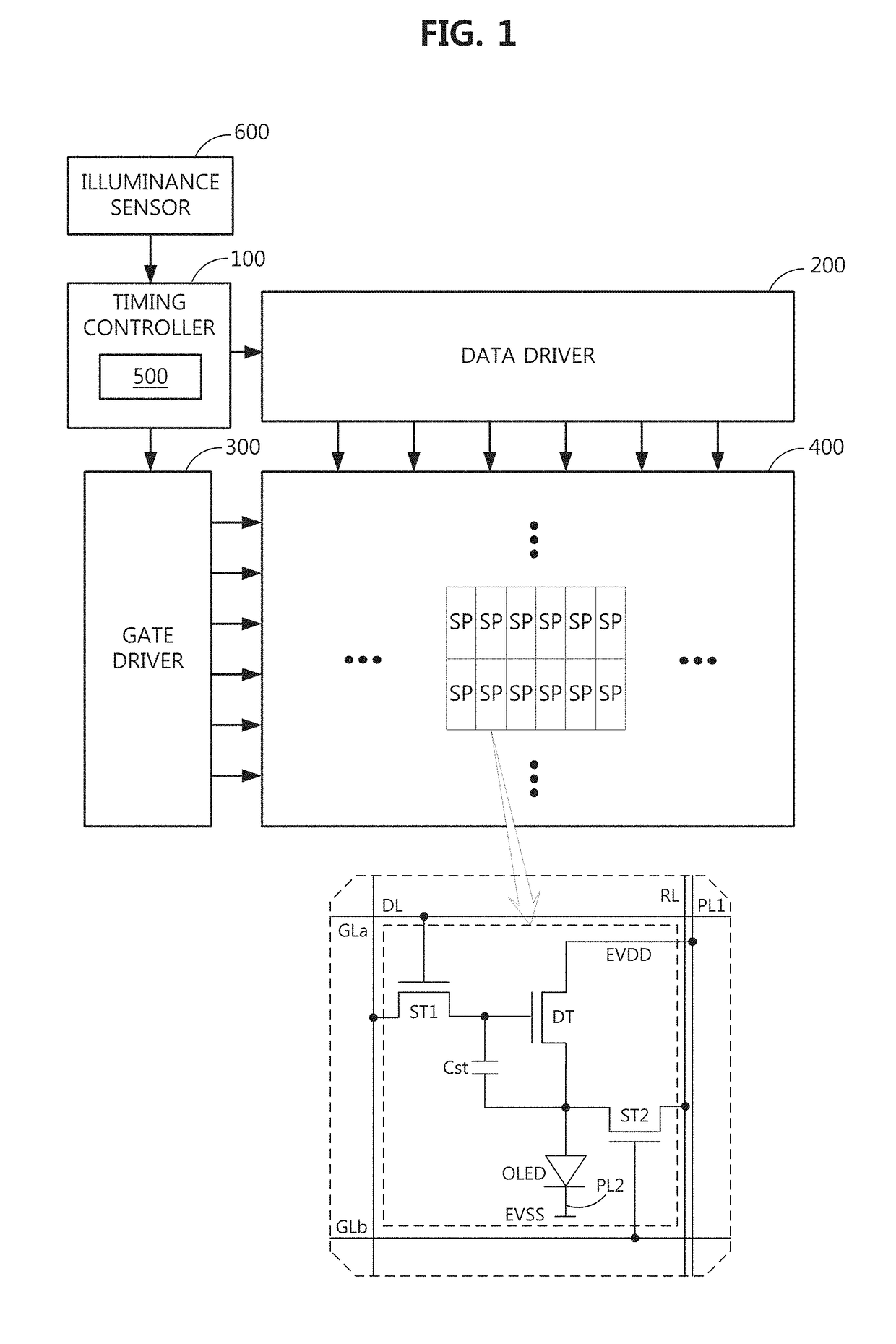
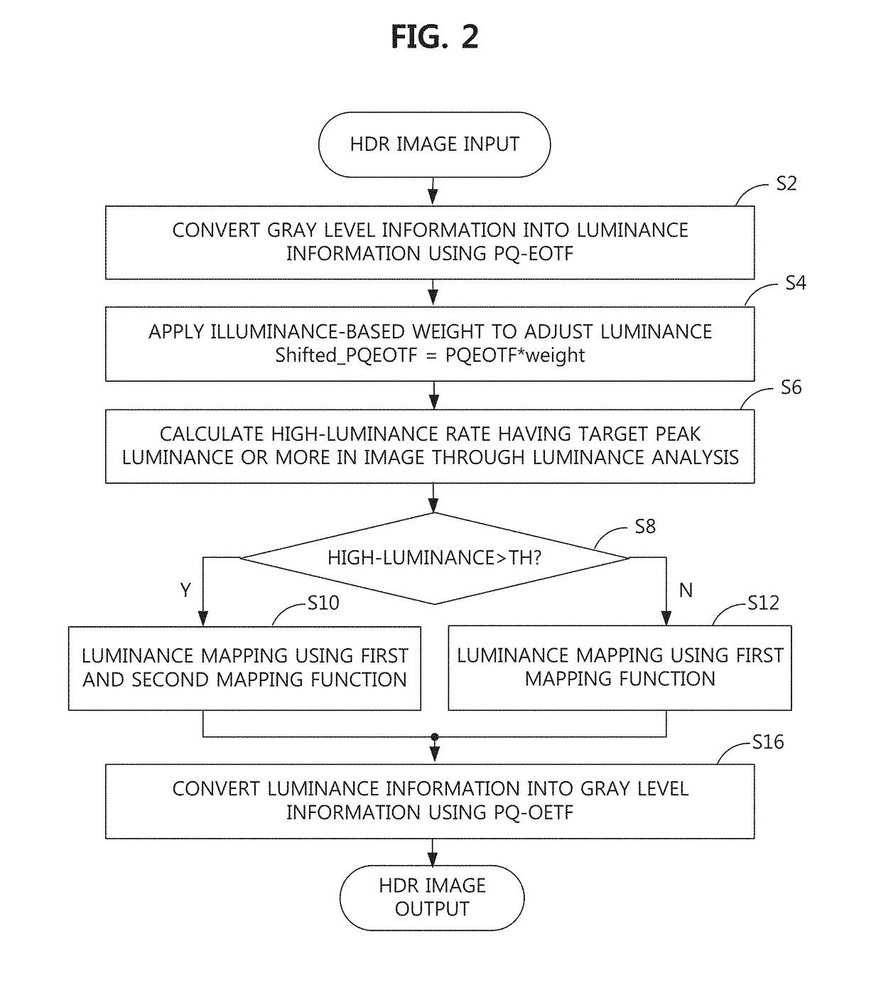
[0029]FIG. 1 is a schematic block diagram showing the configuration of an HDR display device according to an embodiment of the present invention. FIG. 2 is a flowchart illustrating an HDR image processing method according to an embodiment of the present invention. All the components of the HDR display device according to all embodiments of the present invention are operatively coupled and configured.

[0030]The HDR display device shown in FIG. 1 includes a timing controller 100 having an image processing module 500, a data driver 200 and a gate driver 300 as panel drivers, a display panel 400, the image processing module 500, an illuminance sensor 600, a power supply, a gamma voltage generator, etc.

[0031]The display panel 400 displays an image through a pixel array in which pixels are arranged in a matrix. Basic pixels may be composed of at least three subpixels (W / R / G, B / W / R, G / B / W, R / G / B or W / R / G / B) enabling white expression by color mixture of white (W), red (R), green (G) and blue...


PUM


Abstract

A method, display device and module for processing a high dynamic range (HDR) image, are capable of improving visibility according to illuminance. In one embodiment, illuminance information sensed through an illuminance sensor is received, a perceptual quantizer electro-optical transfer function (PQ-EOTF) is adjusted, and gray level information of a first HDR image is converted into luminance information of a second HDR image using the adjusted PQ-EOTF. The luminance information of the second HDR image is analyzed to calculate a high-luminance rate of occupancy of pixels having target peak luminance or more of a display device in the second HDR image. The second HDR image is luminance-mapped to a third HDR image suitable for the display device using a mapping function changed according to the high-luminance rate.

Description

CROSS-REFERENCE TO RELATED APPLICATIONS[0001]This application claims the priority benefit of Korean Patent Application No. 10-2016-0143894, filed on Oct. 31, 2016 in Republic of Korea, which is hereby incorporated by reference in its entirety.BACKGROUND OF THE INVENTIONField of the Invention[0002]The present invention relates to a method and module for processing a high dynamic range (HDR) image, which are capable of improving visibility according to illuminance, and a display device using the same.Discussion of the Related Art[0003]Human beings can perceive a wide brightness range of about 10−6 to 108 nits (cd / m2) and high dynamic range (hereinafter, HDR) technology considering the same has extended to image creation, display development, etc., in addition to photography.[0004]An HDR image is encoded using a perceptual quantizer opto-electrical transfer function (hereinafter, PQ-OETF) defined by the society of motion picture and television engineers (SMPTE) ST. 2084 and has a high ...

Claims


Application Information

Patent Timeline
Patent Type & Authority Applications(United States)
IPC IPC(8): G06T5/00G06T5/50H04N5/232G06T7/136H04N23/76
CPCG06T5/009G06T7/136H04N5/23293G06T5/50G06T2207/20208H04N23/63H04N23/76H04N23/71G06T5/90G09G3/2092G09G5/005G09G5/006H04N5/58G09G2320/0271G09G2320/06G09G2320/062G09G2320/066G09G2320/0666G09G2320/0673G09G2360/144G09G2360/16G09G2340/0428H04N23/741G06T5/92
Inventor KANG, YOO-JINKIM, SUNG-JIN
Owner LG DISPLAY CO LTD
Learn More