
Magnetic recording medium

Active Publication Date: 2018-05-03
FUJI ELECTRIC CO LTD
View PDF2 Cites 4 Cited by
  • Summary
  • Abstract
  • Description
  • Claims
  • Application Information

AI Technical Summary

Benefits of technology

The patent text describes a way to make a magnetic recording medium with a layer that can hold information perpendicular to the surface. This is important because it allows for more data to be stored on the medium. The method involves using a specific alloy that has a preferred orientation for magnetic recording, even when using a special seed layer that was previously thought to be difficult to use. This results in a more effective and reliable magnetic recording medium.

Problems solved by technology

On the other hand, the reduction in the grain diameter of the magnetic crystal grains leads to a decrease in thermal stability of the recorded magnetization (signals).
However, it is considered difficult to use a seed layer consisting of Ru and having (002)-oriented hcp structure, in the case where the magnetic recording layer comprising the L10 ordered alloy is formed.

Method used


Image

  • Magnetic recording medium
  • Magnetic recording medium
  • Magnetic recording medium

Examples


example 1

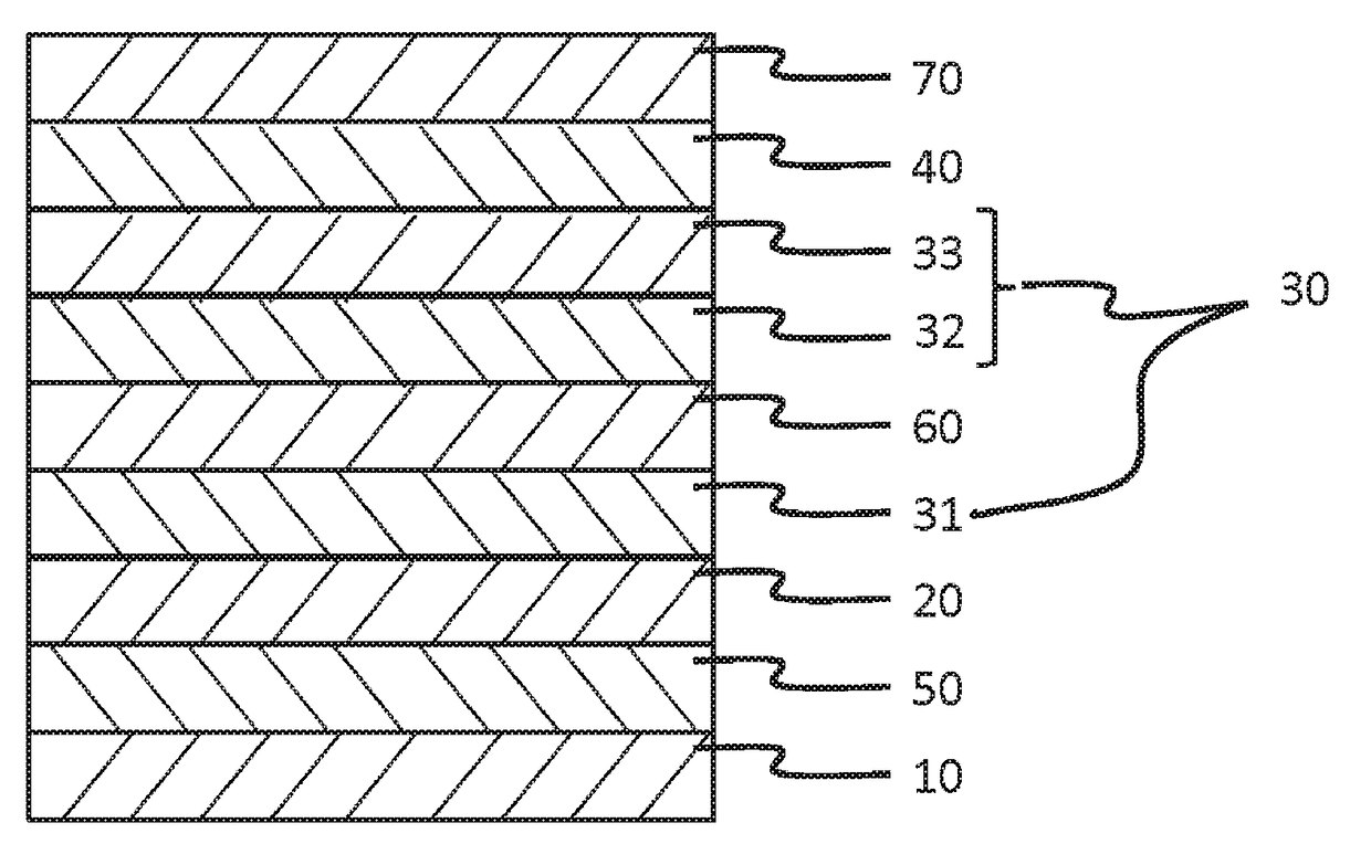
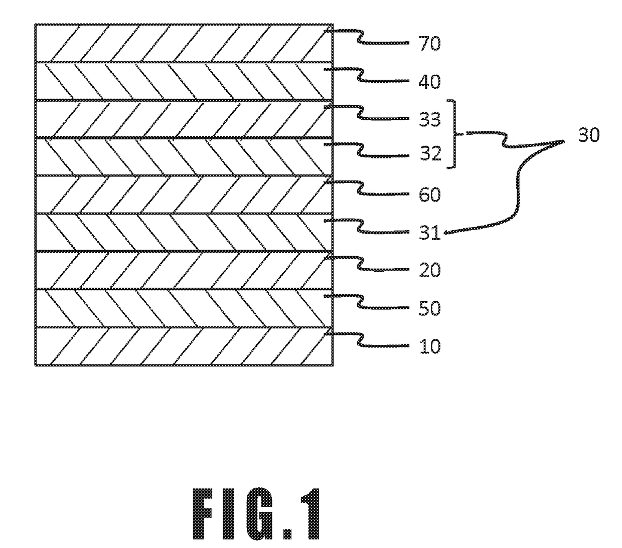
[0035]This example relates to a magnetic recording medium having seed layer 30 of a three-layered structure consisting of Ru first seed layer 31, ZnO second seed layer 32, and MgO third seed layer 33. First, a chemically strengthened glass substrate having a smooth surface (N-10 glass substrate manufactured by HOYA CORPORATION) was washed to prepare substrate 10. The washed substrate 10 was brought into a sputtering device. Then, CrTi adhesive layer having a thickness of 15 nm was formed by a DC magnetron sputtering method using a CrTi target in Ar gas at a pressure of 0.3 Pa. The substrate temperature in forming the CrTi adhesive layer was room temperature (25° C.). The sputtering power in forming the CrTi adhesive layer was 200 W.

[0036]Next, an NiTaAl film having a thickness of 4 nm was formed by a DC magnetron sputtering method using an NiTaAl target in Ar gas at a pressure of 0.3 Pa. The substrate temperature in forming the NiTaAl film was room temperature (25° C.). The sputteri...

example 2

[0043]This example relates to a magnetic recording medium having seed layer 30 of a four-layered structure consisting of Ru first seed layer 31, non-magnetic intermediate layer 60, ZnO second seed layer 32, and MgO third seed layer 33.

[0044]The layers up to the Ru first seed layer 31 was formed by repeating the procedure of Example 1. Subsequently, Pt non-magnetic intermediate layer 60 having a thickness of 10 nm was formed by a DC magnetron sputtering method using a Pt target in Ar gas at a pressure of 0.3 Pa. The substrate temperature in forming the Pt non-magnetic recording layer was room temperature (25° C.). The sputtering power in forming the Pt non-magnetic recording layer was 200 W.

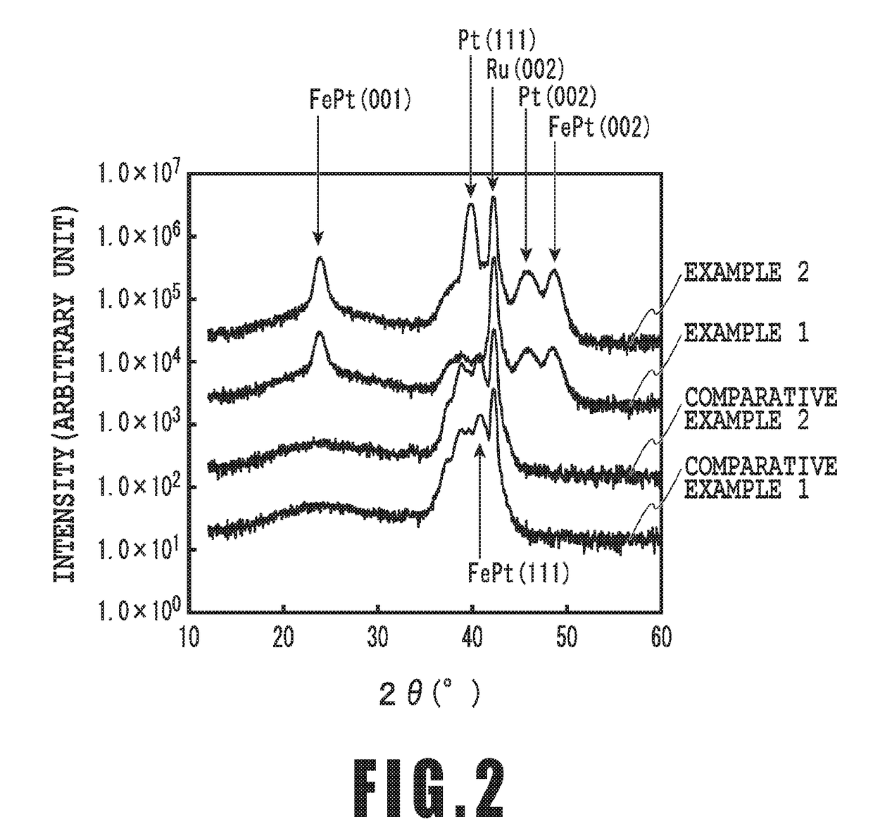
[0045]Subsequently, the ZnO second seed layer 32, the MgO third seed layer 33, the FePt magnetic recording layer 40 and the protective layer 70 were formed by repeating the procedure of Example 1, to obtain a magnetic recording medium. The XRD spectrum of the resultant magnetic recording medium is...


PUM

PropertyMeasurementUnit
Magnetismaaaaaaaaaa
Grain boundaryaaaaaaaaaa

Abstract

The purpose of the present invention is to provide a perpendicular magnetic recording medium which uses an Ru seed layer having a (002)-oriented hcp structure, and has a magnetic recording layer including a (001)-oriented L10 ordered alloy suitable to perpendicular magnetic recording. The magnetic recording medium of the present invention includes a substrate, a first seed layer containing Ru, a second seed layer containing ZnO, a third seed layer containing MgO, and a magnetic recording layer containing an ordered alloy, in this order, the first seed layer having the (002)-oriented hexagonal closest packed structure.

Description

CROSS-REFERENCE TO RELATED APPLICATIONS[0001]This application is a continuation application of PCT Application No. PCT / JP2017 / 000160 filed on Jan. 5, 2017 under 37 Code of Federal Regulation § 1.53 (b) and the PCT application claims the benefit of Japanese Patent Application No. 2016-003577 filed on Jan. 12, 2016, all of the above applications being hereby incorporated by reference wherein in their entirety.BACKGROUND OF THE INVENTIONField of the Invention[0002]The present invention relates to a magnetic recording medium. In particular, the present invention relates to a magnetic recording medium used in a hard disc magnetic recording device (HDD).Description of the Related Art[0003]Perpendicular magnetic recording system is adopted as a technique for achieving high-density magnetic recording. A perpendicular magnetic recording medium at least comprises a non-magnetic substrate and a magnetic recording layer formed of a hard-magnetic material. Optionally, the perpendicular magnetic ...

Claims


Application Information

Patent Timeline
IPC IPC(8): G11B5/73C03C17/36G11B5/65
CPCG11B5/732C03C17/3605C03C17/3639C03C17/3642C03C17/3649G11B5/653C03C2217/216C03C2217/228C03C2217/254C03C2217/258C03C2217/252C03C2217/261C03C2217/259C03C2218/156G11B5/7379G11B5/7369G11B5/737G11B5/657G11B5/658
Inventor UCHIDA, SHINJINAKATA, HITOSHIMORIYA, TOMOHIROFURUTA, AKIRASHIMATSU, TAKEHITO
Owner FUJI ELECTRIC CO LTD
Learn More