
Memory device and clock training method thereof

a memory device and clock technology, applied in the field of memory devices and clock training methods, can solve problems such as insufficient margin of operation

Active Publication Date: 2018-05-03
SAMSUNG ELECTRONICS CO LTD
View PDF7 Cites 12 Cited by
  • Summary
  • Abstract
  • Description
  • Claims
  • Application Information

AI Technical Summary

Benefits of technology

The patent is about a training method and a memory device that can synchronize control signals with a clock signal. By using a memory controller to provide a clock signal to a memory device, the control signal can be synchronized with the clock signal. The synchronization is done by finding a failure time point where the memory device fails to sample the control signal. The failure time point is based on the clock signal and the control signal. This synchronization allows for more efficient training of the memory device and ensures accurate performance. The memory device can also include an internal clock buffer that generates an internal clock signal based on an input from the host, an input buffer, a sampler, and a command address latch. The training operation can be initiated by the host, and the control signal and command signal can be synchronized with the internal clock signal. Overall, this patent provides a more efficient and reliable training method for memory devices.

Problems solved by technology

Accordingly, if the memory device performs the normal operation after the training is completed, data that is exchanged between the application processor and the memory device while the margin of operation is smaller than that for the training operation is secured are synchronized at an unintended edge of a clock signal, or the margin of operation may be insufficient.

Method used


Image

  • Memory device and clock training method thereof
  • Memory device and clock training method thereof
  • Memory device and clock training method thereof

Examples


Embodiment Construction

[0018]Below, embodiments of the inventive concept may be described in detail so that a person of ordinary skill in the art can practice the inventive concept.

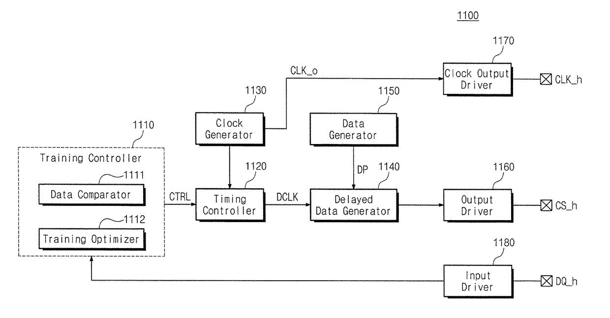
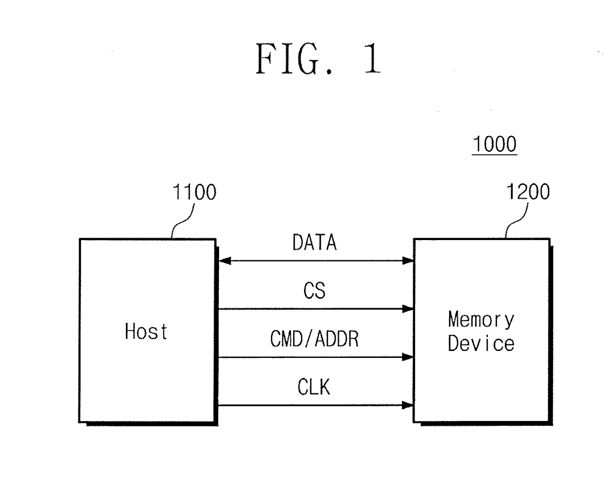
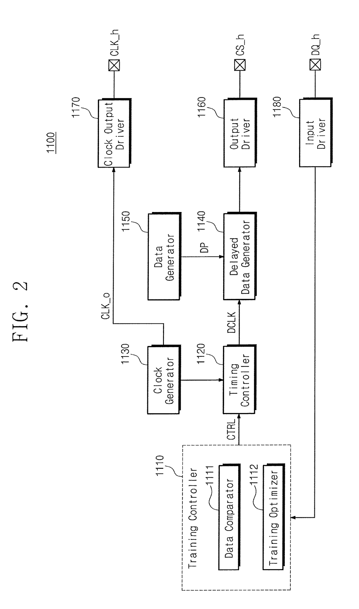
[0019]FIG. 1 is a block diagram illustrating a memory system, according to an embodiment of the inventive concept. Referring to FIG. 1, a memory system 1000 may include a host 1100 and a memory device 1200. For example, the memory system 1000 may be a single system that includes both the host 1100 and the memory device 1200. Alternatively, the host 1100 and the memory device 1200 of the memory system 1000 may be implemented with separate devices, respectively.

[0020]The host 1100 may be a processor circuit or system that includes a general-purpose processor or an application processor. Alternatively, the host 1100 may be, for example, the following: a computing device including one or more processors: a personal computer, a peripheral device, a digital camera, a personal digital assistant (PDA), a portable media player (PMP), a ...


PUM


Abstract

A training method for a memory device includes providing, at a memory controller, a clock signal to the memory device to synchronize a control signal at a reference time point of the clock signal. When the clock signal, such as a training clock signal, does not transition after the reference time point, a failure time point is found at which the memory device fails to sample the control signal at the reference time point, based on the clock signal and the control signal. A synchronization time point of the control signal may be set, at which the memory device secures a sampling margin for sampling the control signal at the reference time point, based on the failure time point. A sampler circuit may sample the control signal at an edge of a rising edge of the clock signal.

Description

CROSS-REFERENCE TO RELATED APPLICATIONS[0001]This application claims priority under 35 U.S.C. § 119 from Korean Patent Application No. 10-2016-0141207 filed Oct. 27, 2016, in the Korean Intellectual Property Office, the entire contents of which are hereby incorporated by reference herein.TECHNICAL FIELD[0002]Embodiments of the inventive concept disclosed herein relate to a semiconductor memory device, and in particular, to a memory device and a training method thereof.DISCUSSION OF THE RELATED ART[0003]There has been a dramatic increase in the use of mobile devices such as a smartphone, a tablet personal computer (PC), a digital camera, an MP3 player, personal digital assistant (PDA), and a wearable device. According to recent mobile trends, high integration, high performance, and low power are required for a semiconductor memory device for use in the mobile device.[0004]An operating speed of a high-performance memory device is significantly faster than other types of memory devices...

Claims


Application Information

Patent Timeline
Patent Type & Authority Applications(United States)
IPC IPC(8): G11C16/32H10B69/00
CPCG11C16/32G11C2207/2281G11C2207/229G11C2207/2245G11C7/222G11C29/023G11C29/028G11C2207/2254G06F13/1689G11C11/4076
Inventor CHOI, YEONKYUSHIN, SEUNGJUN
Owner SAMSUNG ELECTRONICS CO LTD
Learn More