Electrified Aircraft and Method of Controlling Regenerative Electric Power of Electrified Aircraft

a technology of electrified aircraft and regenerative electric power, which is applied in the direction of aircraft, sustainable transportation, transportation and packaging, etc., can solve the problems of inability to control the path angle or the descending rate directly, the workload of the pilot is significantly increased, and the operation tends to be complex, so as to maximize the safe generation of electric power and good response

Active Publication Date: 2018-05-10
JAPAN AEROSPACE EXPLORATION AGENCY
View PDF0 Cites 16 Cited by
  • Summary
  • Abstract
  • Description
  • Claims
  • Application Information

AI Technical Summary

Benefits of technology

[0036]According to the present invention, by estimating the drag force of the propeller or the fan based on the propulsion system parameters of the electric drive motor, the path angle and the descending rate can be controlled with a good response independently from a speed while controlling the drag force of the propulsion system and it is possible to maximize safely a generated electric power in each flight status at the time of descent or ascent.

Problems solved by technology

Accordingly, the operation tends to be complex.
In addition, once gusty wind attacks the aerodynamic device, workloads of a pilot significantly increase, thereby causing safety issues.
This is because an existing aerodynamic device changes not only a drag force but also a lift force of the airframe and the path angle or the descending rate cannot be controlled directly.

Method used


Image

  • Electrified Aircraft and Method of Controlling Regenerative Electric Power of Electrified Aircraft
  • Electrified Aircraft and Method of Controlling Regenerative Electric Power of Electrified Aircraft
  • Electrified Aircraft and Method of Controlling Regenerative Electric Power of Electrified Aircraft

Examples


first embodiment

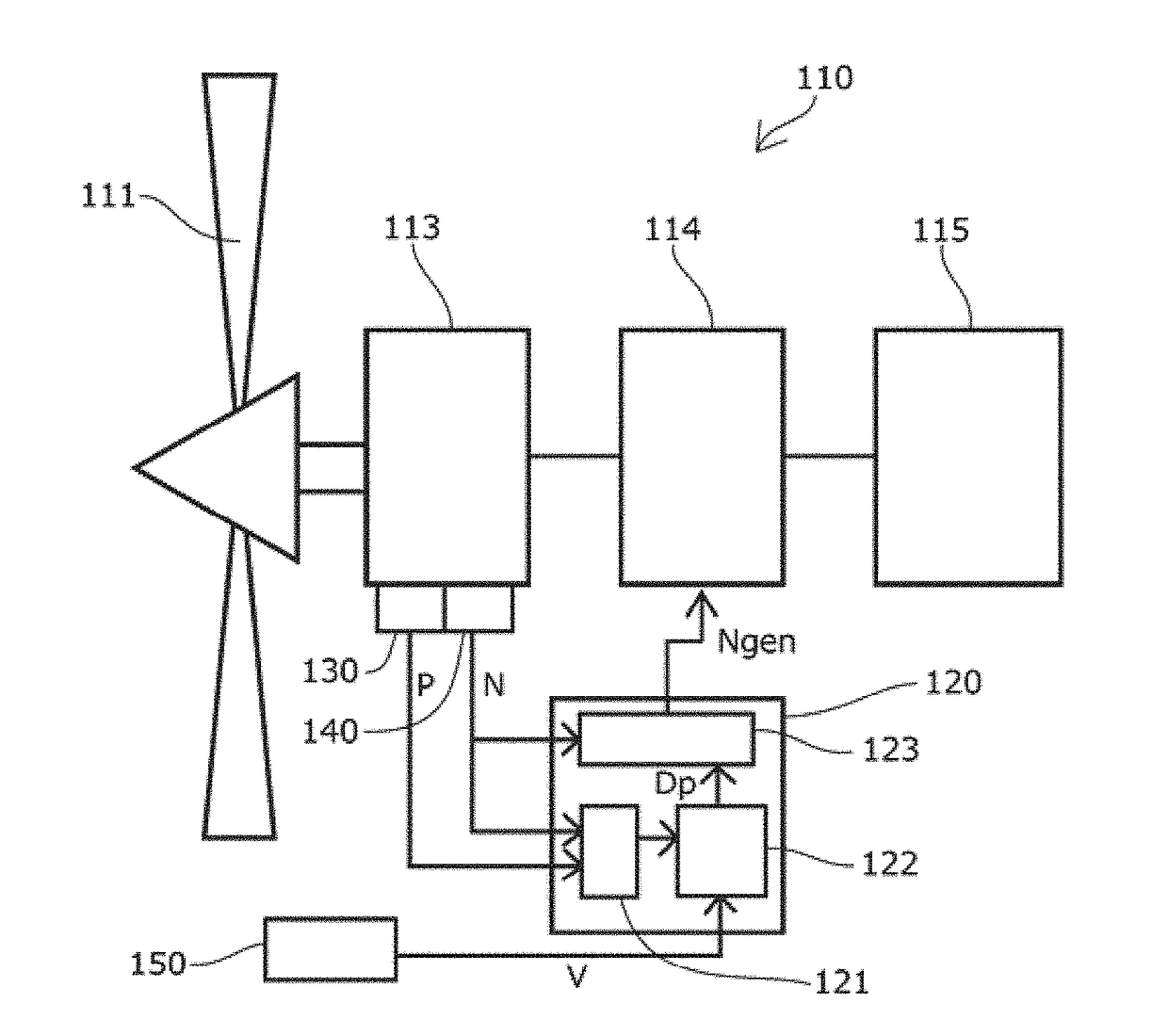
[0121]FIG. 1 is an explanatory diagram of a propulsion drive system of an electrified aircraft according to a first embodiment of the present invention.

[0122]As shown in FIG. 1, a propulsion drive system 110 of the electrified aircraft is configured such that a propeller 111 is driven by an electric drive motor 113, or the electric drive motor 113 generates electric power by rotating the propeller 111.

[0123]The electric drive motor 113 is driven by electric power supplied from an electric power source 115 such as a storage battery, or generates electric power to supply the electric power to the electric power source115, and an inverter 114 controls the electric power.

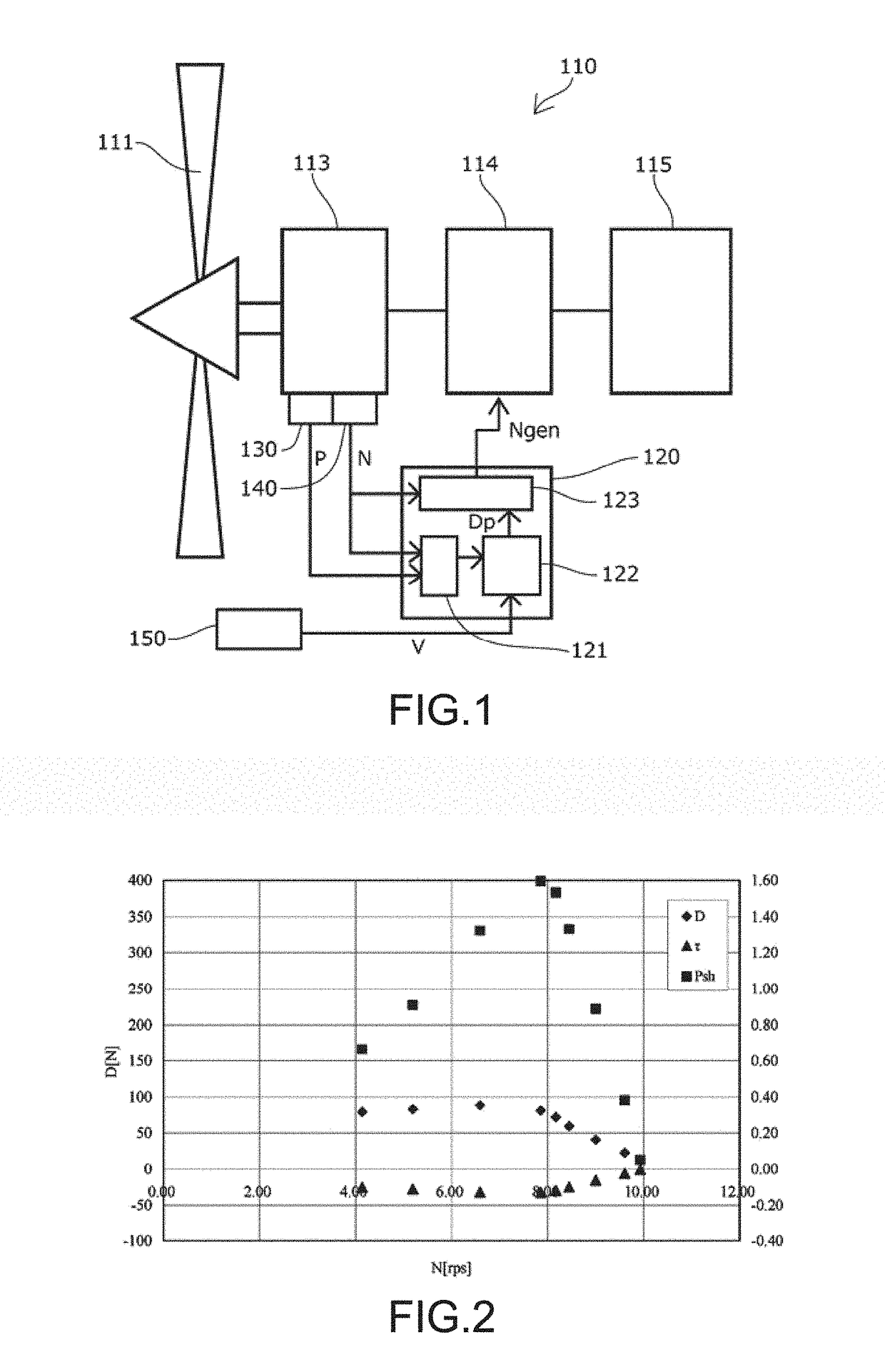
[0124]A control unit, i.e., a drive control means 120, includes inside data groups relating to a relationship between a rotation number Ngen and a drag force Dp of a propeller specific to an individual electrified aircraft as shown in FIG. 2. At the time of generating an electric power, a drag operation unit 122 estimat...

second embodiment

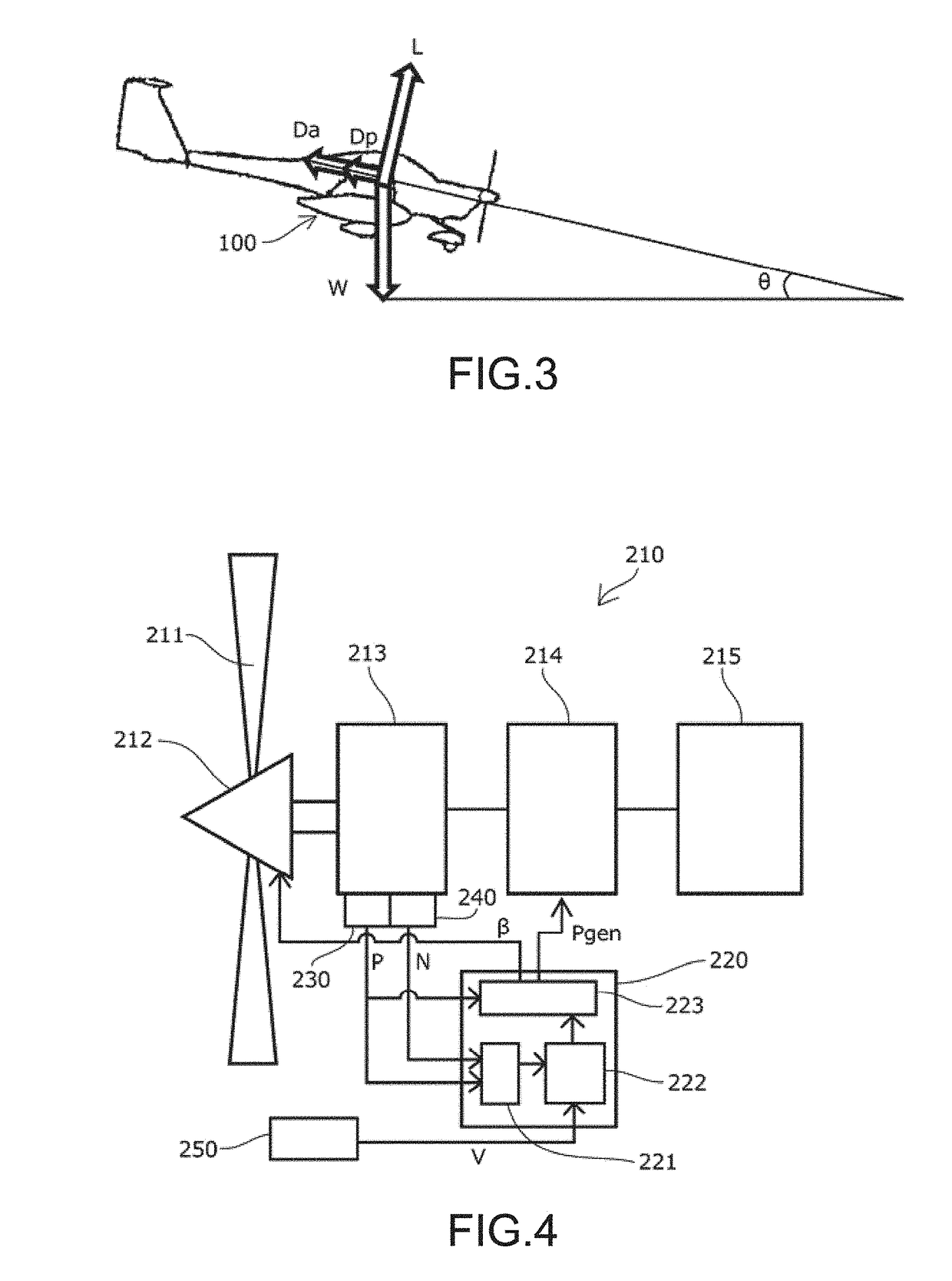
[0133]FIG. 4 is an explanatory diagram of a propulsion drive system of an electrified aircraft according to a second embodiment of the present invention.

[0134]As shown in FIG. 4, a propulsion drive system 210 of the electrified aircraft is configured such that a propeller 211 is driven by an electric drive motor 213, or the electric drive motor 213 generates electric power by rotating the propeller 211 similar to the first embodiment.

[0135]The electric drive motor 213 is driven by electric power supplied from an electric power source 215 such as a storage battery, or generates electric power to supply the electric power to the electric power source 215, and an inverter 214 controls the electric power.

[0136]In this embodiment, the propeller 211 is a variable pitch propeller including a variable pitch mechanism 212, and the variable pitch mechanism 212 has a function to change a pitch angle β from a pitch angle βTO used at a take-off to a pitch angle β0 that is smaller than the pitch ...

third embodiment

[0143]FIG. 7 is an explanatory diagram of a propulsion drive system of an electrified aircraft according to a third embodiment of the present invention.

[0144]As shown in FIG. 7, a propulsion drive system 310 of the electrified aircraft is configured such that a propeller 311 is driven by an electric drive motor 313, or the electric drive motor 313 generates electric power by rotating the propeller 311 similar to the second embodiment.

[0145]The electric drive motor 313 is driven by electric power supplied from an electric power source 315 such as a storage battery, or generates electric power to supply the electric power to the electric power source 315, and an inverter 314 controls the electric power.

[0146]The propeller 311 is a variable pitch propeller including a variable pitch mechanism 312, and the variable pitch mechanism 312 has a function to change the pitch angle β from the pitch angle βTO used at a take-off to the pitch angle β0 that is smaller than the pitch angle βTO.

[014...


PUM


Abstract

To provide an electrified aircraft, and a method of controlling a regenerative electric power of the electrified aircraft where a path angle and a descending rate can be controlled with a good response independently from a speed while controlling the drag force of the propulsion drive system and where it is possible to maximize safely a generated electric power in each flight status at the time of descent or ascent. The electrified aircraft includes a propeller or a fan for propulsion; an electric drive motor for rotary-driving the propeller or the fan and for generating an electric power by the rotation of the propeller or the fan; and an estimation unit for estimating a drag force of the propeller or the fan or an electric power generation amount of the electric drive motor based on propulsion system parameters of the electric drive motor.

Description

CROSS-REFERENCE TO RELATED APPLICATIONS[0001]This application is the U.S. national stage application of International Patent Application No. PCT / JP2015 / 057317, filed Mar. 12, 2015; which claims priority to Japanese Application Nos. 2014-064584, filed Mar. 26, 2014; 2014-064585, filed Mar. 26, 2014; and 2014-064586, filed Mar. 26, 2014, the disclosures of each of which are incorporated herein by reference in their entirety.TECHNICAL FIELD[0002]The present invention relates to an electrified aircraft having a propulsion drive system driven by an electric drive motor, and a method of controlling a regenerative electric power of the electrified aircraft.BACKGROUND ART[0003]In a general aircraft, an aerodynamic device such as an elevator and a spoiler is used for adjusting a path angle at the time of descent so that an airframe is not deviated from a desirable path.[0004]The aerodynamic device may change both of the path angle and an airspeed.[0005]For example, as shown in FIG. 29, the a...

Claims


Application Information

Patent Timeline
Patent Type & Authority Applications(United States)
IPC IPC(8): B64D27/24
CPCB64D27/24B64C2201/021Y02T10/72Y02T50/60B64U10/25
Inventor KOBAYASHINISHIZAWA, AKIRAIIJIMA, TOMOKOTAGASHIRA, TAKESHI
Owner JAPAN AEROSPACE EXPLORATION AGENCY
Why Eureka
Try Eureka