Support providing a complete connection between a turbine shaft and a degassing pipe of a turbojet

a technology of degassing pipe and turbine shaft, which is applied in the direction of machines/engines, mechanical equipment, couplings, etc., can solve the problems of cracks on the scratches on the inner surface of the turbine shaft, and achieve the effect of preventing cracks

Active Publication Date: 2018-05-10
SN DETUDE & DE CONSTR DE MOTEURS DAVIATION S N E C M A
View PDF0 Cites 7 Cited by
  • Summary
  • Abstract
  • Description
  • Claims
  • Application Information

AI Technical Summary

Benefits of technology

[0009]In particular, one of the aims of the invention is to prevent the deterioration of the turbine shaft following scratches.
[0010]Another aim of the invention is to facilitate the assembly of the support systems in the turbine shaft, thus reducing the duration and incidentally the cost of operations.
[0011]Another aim is to facilitate the disassembly of the systems, thus reducing the risks of deterioration during maintenance operations.

Problems solved by technology

During the installation of the support systems, it happens that scratches occur on the inner surface of the turbine shaft.
The wear caused by the operating conditions of the turbine shaft bring cause cracks to form on these scratches.
This deterioration of the structure of the turbine shaft may cause it to rupture.

Method used


Image

  • Support providing a complete connection between a turbine shaft and a degassing pipe of a turbojet
  • Support providing a complete connection between a turbine shaft and a degassing pipe of a turbojet
  • Support providing a complete connection between a turbine shaft and a degassing pipe of a turbojet

Examples


Embodiment Construction

[0032]General

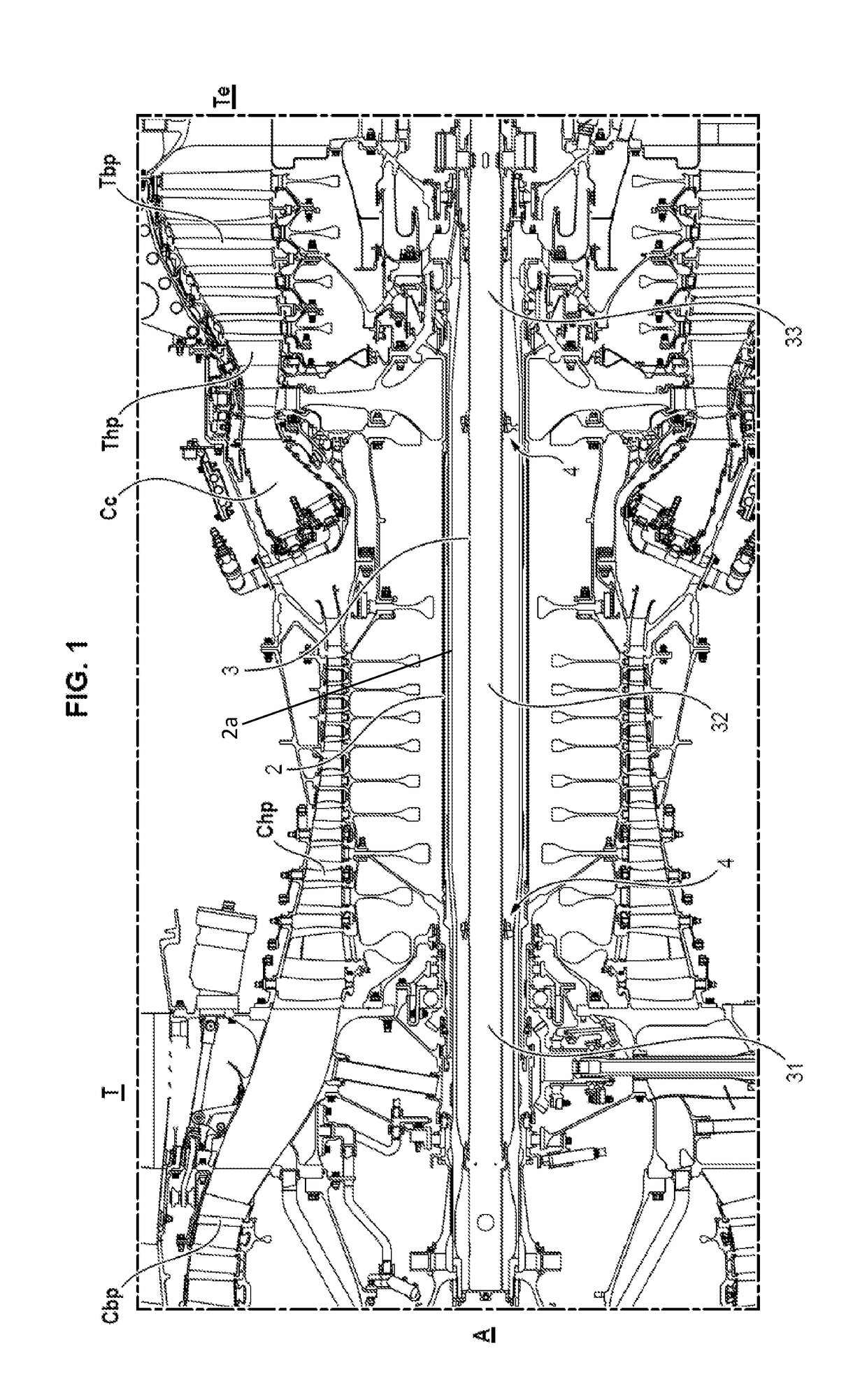
[0033]With reference to FIG. 1, a turbojet T conforming to an embodiment of the invention includes, conventionally, a low-pressure compressor Cbp, a high-pressure compressor Chp, a combustion chamber Cc, a high-pressure turbine Thp, a low-pressure turbine Tbp and an exhaust nozzle Te.

[0034]The turbine shaft 2 extends along an axis A which is the overall axis of the turbojet T. The concepts of longitudinal and radial hereafter in the description will be relative to this axis A. The concepts of upstream and downstream hereafter in the description will be relative to the direction of flow of the fluids in the degassing pipe.

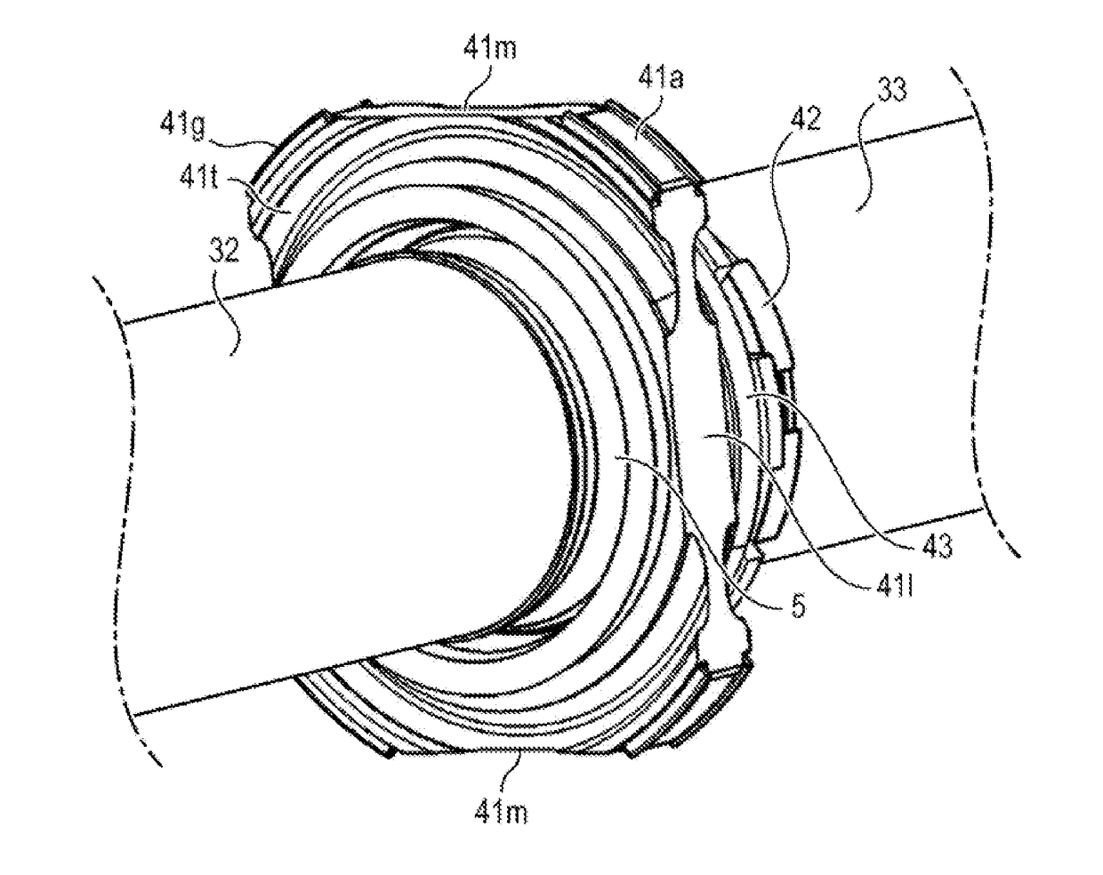
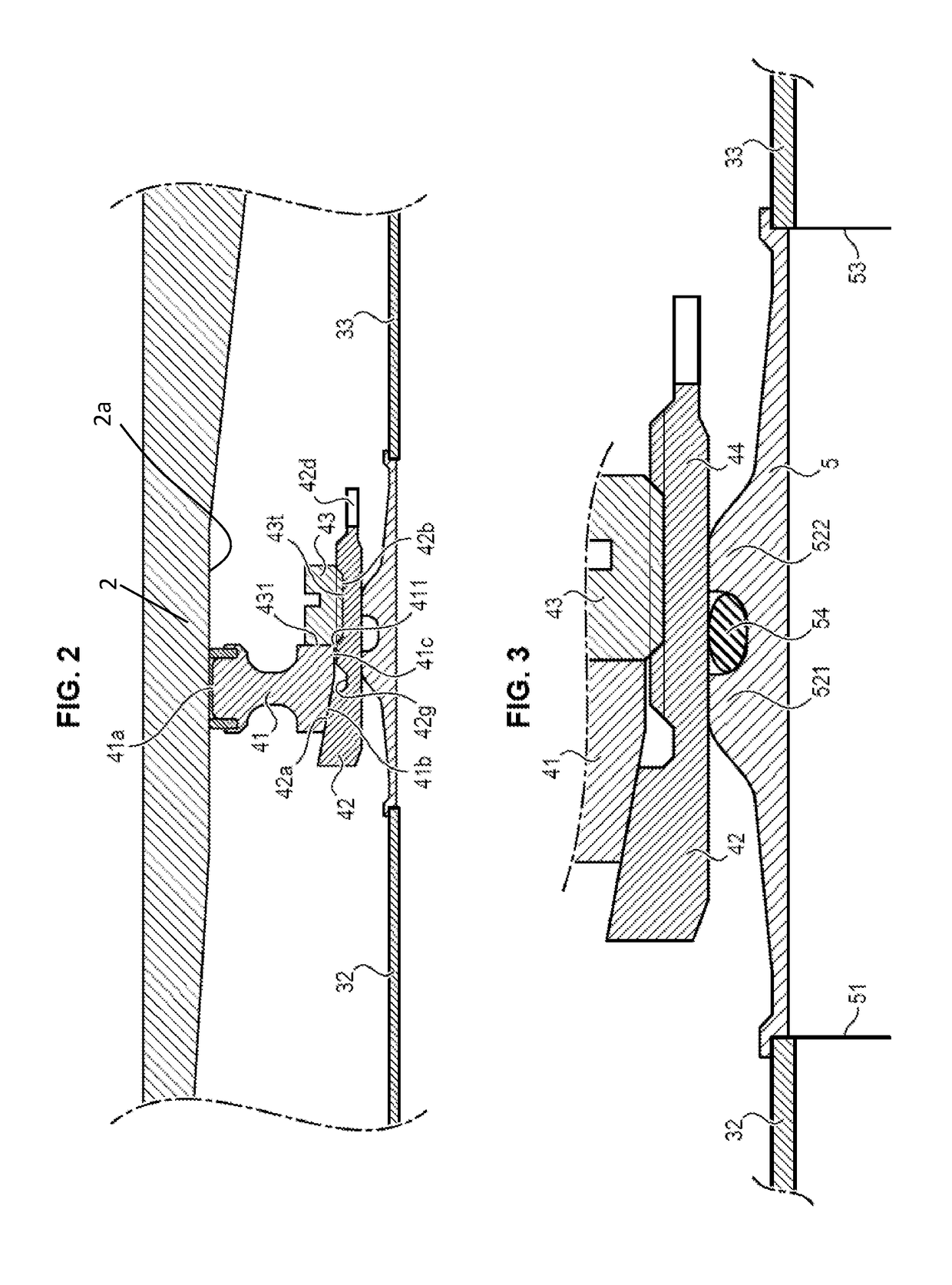
[0035]The turbine shaft 2 is hollow, and includes an inner wall 2a.

[0036]A degassing pipe 3 extends within the turbine shaft 2. Its function is to guide downstream the ventilation gas flow of the rolling element.

[0037]The degassing pipe 3 extends along the axis of the turbojet, concentrically with the turbine shaft 2. It is hollow and axially symmetric...


PUM


Abstract

The invention relates to a support providing a complete connection between a degassing pipe (3) and a turbine shaft (2), said support including a plurality of outer contact spans (41a) intended to bear on the inner walls of the turbine shaft to secure the degassing pipe with respect thereto, characterized in that the different spans are each bordered by at least one elastomer insert (41g) which contributes to the protection of the turbine shaft during insertion of the support therein.

Description

GENERAL TECHNICAL FIELD AND PRIOR ART[0001]The invention relates to a support providing a complete connection between a turbine shaft and a degassing pipe of a turbojet.[0002]The function of lubricating the rolling elements of a turbojet is conventionally provided by an atmosphere including oil droplets in the compartments containing these rolling elements. In order to provide ventilation for them, a gas flow passes through these compartments and then passes through oil separators, the function whereof is to separate the oil from the gasses. The oils are captured by centrifugal effect to then be re-injected into the compartments of the rolling elements.[0003]The gas flow is discharged via a degassing pipe. This is situated within the turbine shaft, concentrically with it. It is connected thereto by one or more insertion connections.[0004]One example of a coupling is for example proposed in patent application FR 2 957 974, in the case of a turbine shaft with a constant inner diameter...

Claims


Application Information

Patent Timeline
Patent Type & Authority Applications(United States)
IPC IPC(8): F02C7/20F01D25/22F16L37/14F16J15/3272
CPCF02C7/20F01D25/22F16L37/144F16J15/3272F05D2230/642F05D2240/61F05D2260/609F01D5/026F01D25/18F05D2230/64
Inventor DURAND, NOEL DIDIERDELAPORTE, DANIEL NICOLASLINQUETTE, EMMANUEL
Owner SN DETUDE & DE CONSTR DE MOTEURS DAVIATION S N E C M A
Why Eureka
Try Eureka