Tensioner

a technology of tensioner and chain, which is applied in the direction of belt/chain/gearing, mechanical equipment, belt/chain/gearing, etc., can solve the problem of chain flapping and achieve the effect of simple structur

Active Publication Date: 2018-05-10
TSUBAKIMOTO CHAIN CO
View PDF20 Cites 0 Cited by
  • Summary
  • Abstract
  • Description
  • Claims
  • Application Information

AI Technical Summary

Benefits of technology

[0010]Yet another design that can be considered is to set the relief valve mechanism 170 described above or the like somewhere else other than the front end of the plunger 120 as shown in FIG. 8 (see, for example, Japanese Patent Application Laid-open No. 2002-327810). In the example shown in FIG. 8, oil leakage from the high oil-pressure chamber 111 (plunger hole 121) to the outside of the plunger 120 when the engine is at a standstill can be prevented even when the plunger 120 is oriented such that its front end is vertically downward.
[0012]The present invention solves these problems and it is an object of the invention to provide a tensioner that can keep the oil pressure inside a first high oil-pressure chamber stable to hold the chain favorably with a simple structure.
[0014]According to one aspect of the present invention, a second high oil-pressure chamber is formed in the housing in addition to the first high oil-pressure chamber, and a relief unit is provided outside the second high oil-pressure chamber. When the plunger is pushed back hard to the rear side by the chain and the oil pressure inside the first high oil-pressure chamber rises, oil inside the second high oil-pressure chamber connected to the first high oil-pressure chamber can be discharged from the relief unit. Therefore, unlike the case where the relief unit is provided at the front end of the plunger, oil leakage from the first high oil-pressure chamber to the outside of the plunger when the engine is at a standstill can be prevented even when the plunger is oriented such that its front end is vertically downward.
[0015]The gap between the inner circumferential surface of the plunger hole and the outer circumferential surface of the inner sleeve is utilized as part of the oil flow passage connecting the first high oil-pressure chamber and the second high oil-pressure chamber. Since such a gap is easily formed to be sufficiently thin and long, the oil flow passage that provides sufficient flow resistance can be formed with a simple structure without the need to perform complex machining on the housing and others. Accordingly, even when the plunger is pushed back hard to the rear side by the chain, pressure can be released from the first high oil-pressure chamber to the second high oil-pressure chamber, so that, while an excessive buildup of oil pressure in the first high oil-pressure chamber is prevented, release of a large amount of oil from the first high oil-pressure chamber is avoided. Thus a sufficient amount of oil can remain in the first high oil-pressure chamber and the oil pressure in the first high oil-pressure chamber is kept stable.
[0016]According to another aspect of the present invention, an oil groove is formed in an outer circumferential surface of a press-fit component pressed into the plunger hole, and the gap between the inner circumferential surface of the plunger hole and the oil groove functions as part of an oil flow passage, so that oil can flow from the first high oil-pressure chamber to the second high oil-pressure chamber radially outside the check valve (press-fit component) while avoiding reverse flow of the oil from the first high oil-pressure chamber to the oil reservoir chamber by the check valve.
[0017]According to another aspect of the present invention, the circumferential position of the second high oil-pressure chamber is matched with the circumferential position of the oil groove, so that the pressure inside the first high oil-pressure chamber can be released smoothly to the second high oil-pressure chamber. Also, since a ratchet meshing with the plunger stops the plunger from rotating, the second high oil-pressure chamber and the oil groove are stopped from displacing out of position relative to each other.

Problems solved by technology

If oil is let out more easily so as to avoid this issue, the plunger 120 will be pushed back rearward even with a slight force, which leads to the problem of chain flapping.

Method used


Image

  • Tensioner
  • Tensioner
  • Tensioner

Examples


Embodiment Construction

[0029]A tensioner 10 according to one embodiment of the present invention will be described with reference to the drawings.

[0030]First, the tensioner 10 is incorporated in a chain drive device used in a timing system or the like of a car engine. The tensioner is attached to an engine block to apply appropriate tension to the slack side of a drive chain passing over a plurality of sprockets via a tensioner lever to reduce vibration during the drive.

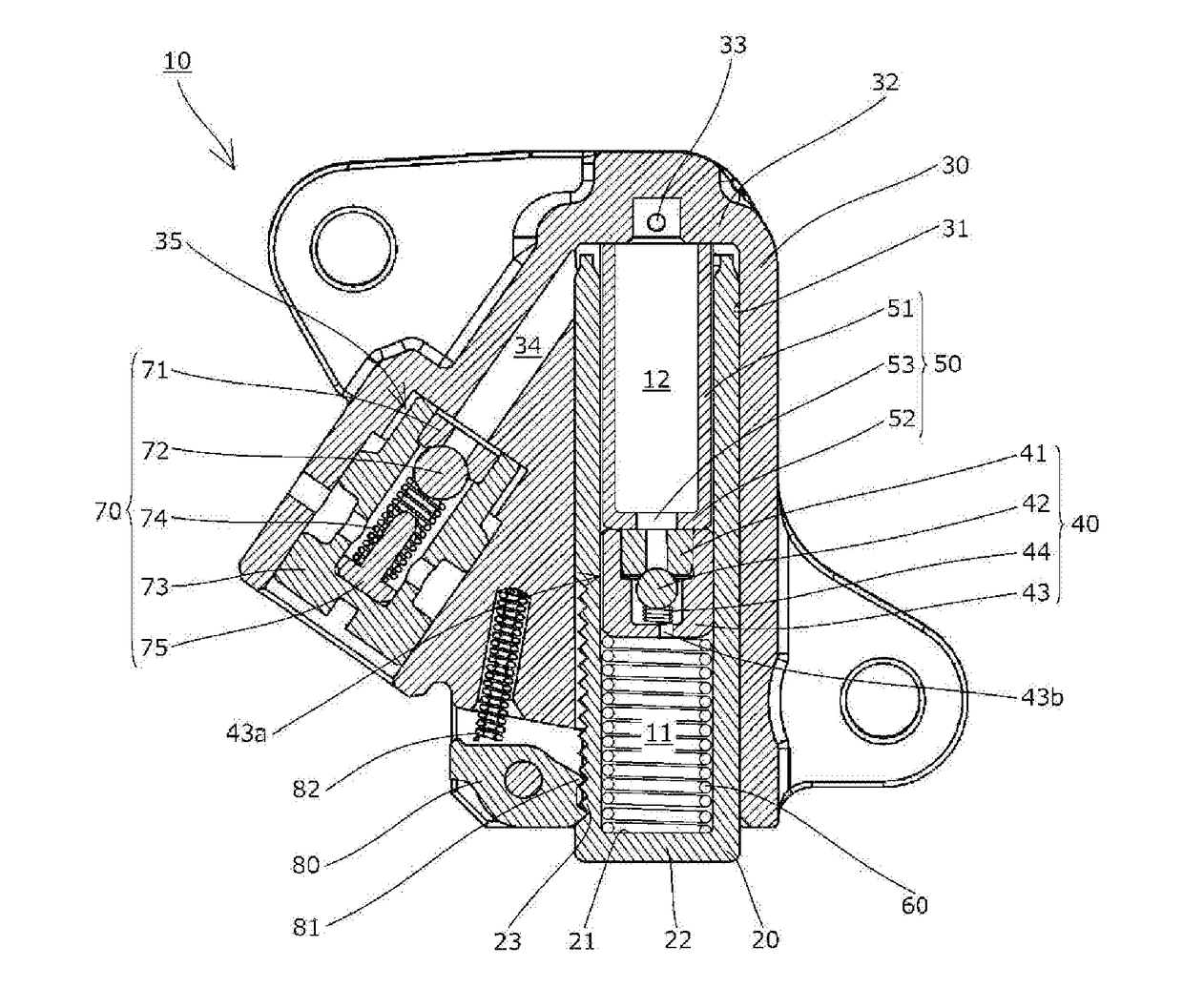
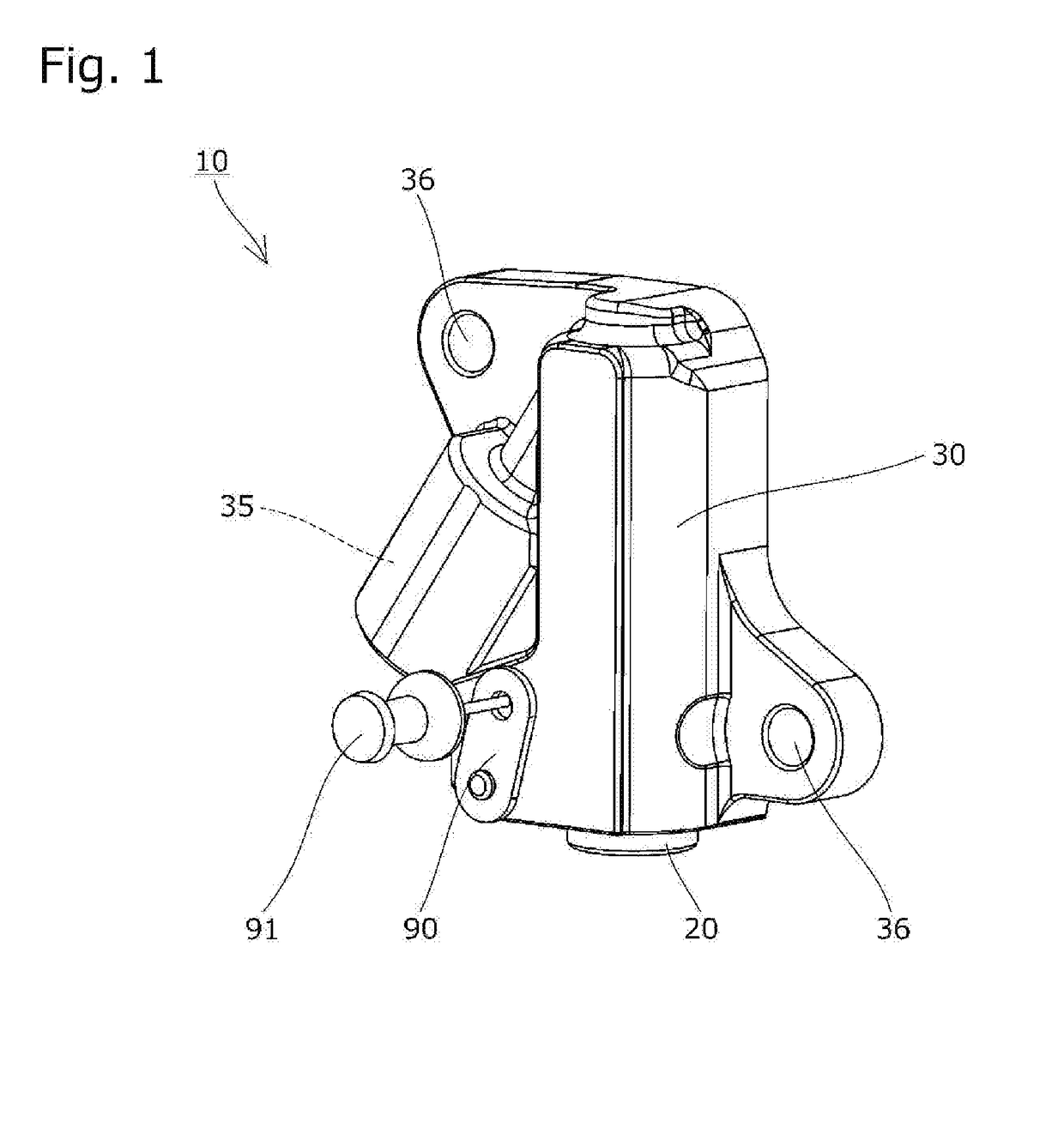
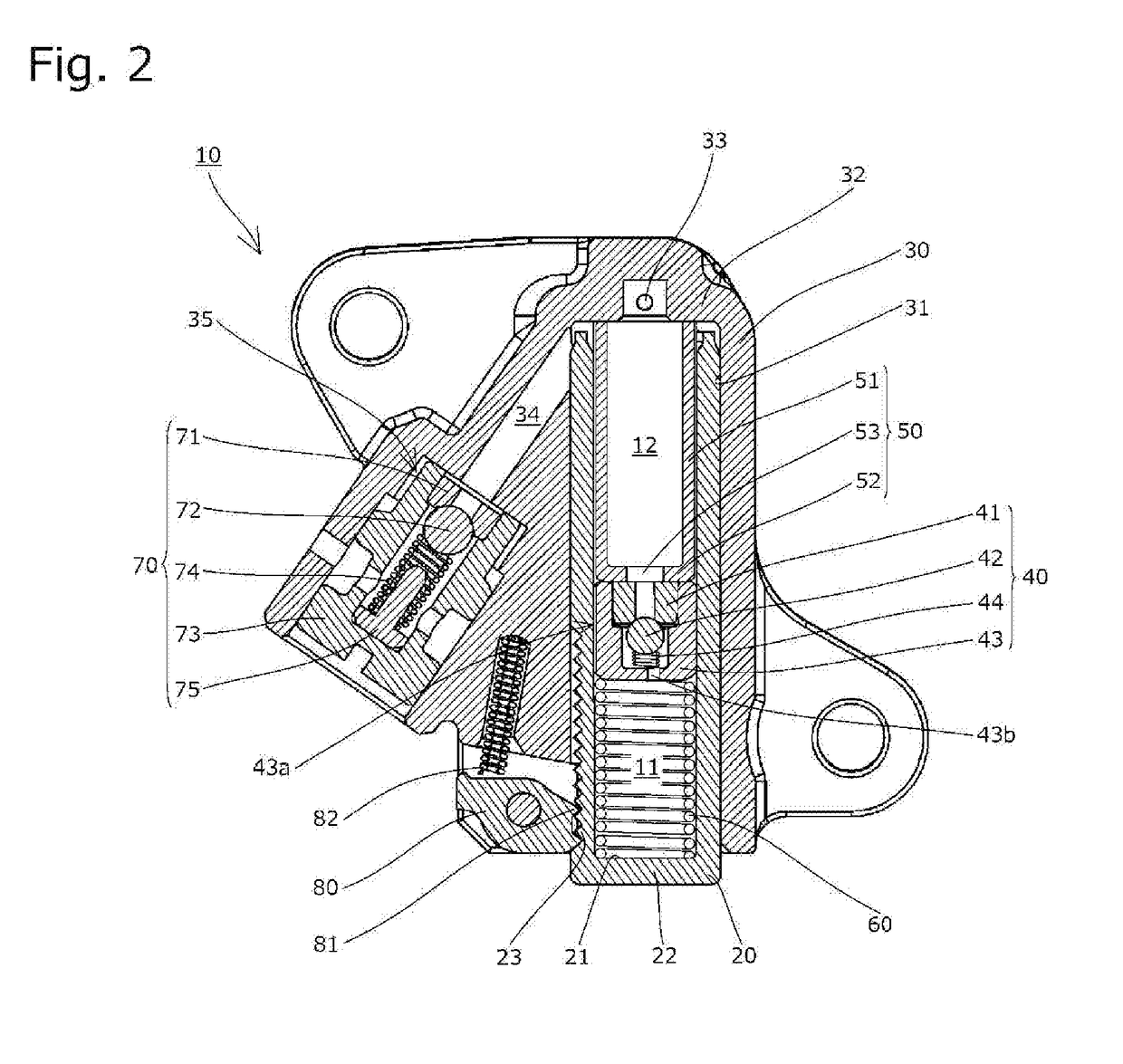
[0031]The tensioner 10 includes, as shown in FIG. 1 and FIG. 2, a cylindrical plunger 20, a housing 30 having a plunger accommodation bore 31 that is open on a front side and accommodates the plunger 20, a check valve 40 arranged inside the plunger accommodation bore 31 and partitioning an internal space formed between the housing 30 and the plunger 20 into a first high oil-pressure chamber 11 on the front side and an oil reservoir chamber 12 on the rear side, an inner sleeve 50 slidably disposed inside the oil reservoir chamber 12, a coil...


PUM


Abstract

A tensioner with a simple structure is provided, which is capable of keeping oil pressure in a first high oil-pressure chamber stable and holding a chain favorably. The tensioner includes a plunger, a housing, a check valve, an inner sleeve, and a biasing member. In the housing, a second high oil-pressure chamber and a unit setting part are formed. In the unit setting part, a relief valve unit is set. A gap between an inner circumferential surface of a plunger hole and an outer circumferential surface of the inner sleeve functions as part of an oil flow passage that connects the first high oil-pressure chamber and the second high oil-pressure chamber.

Description

BACKGROUND OF THE INVENTION1. Field of the Invention[0001]The present invention relates to a tensioner that applies appropriate tension to a running chain, belt, or the like.2. Description of the Related Art[0002]It has been common practice to use a tensioner for maintaining appropriate tension in a chain or the like. For example, a known chain guide mechanism uses a tensioner to bias a tensioner lever for slidably guiding a drive chain, such as an endless roller chain passing over respective sprockets of a crankshaft and a cam shaft inside an engine room, to maintain appropriate tension of the chain or the like.[0003]The known tensioner 110 includes, as shown in FIG. 6, a housing 130 having a plunger accommodation bore 131 open on a front side, a plunger 120 slidably inserted in the plunger accommodation bore 131, and a coil spring (not shown in FIG. 6) that biases the plunger 120 toward the front side. In such a tensioner 110, oil is supplied to a high oil-pressure chamber 111 for...

Claims


Application Information

Patent Timeline
Patent Type & Authority Applications(United States)
IPC IPC(8): F16H7/08
CPCF16H7/0848F16H2007/0814F16H2007/0853F16H2007/0859F16H7/08F16H2007/0812
Inventor NAKATA, YOHEIKUREMATSU, YUJIOGO, TOSHITAKA
Owner TSUBAKIMOTO CHAIN CO
Why Eureka
Try Eureka