RGB combiner using MEMS alignment and PLC

a technology of rgb and combiner, which is applied in the direction of instruments, semiconductor lasers, optical elements, etc., can solve the problems of assembly alignment and occupying a lot of spa

Inactive Publication Date: 2018-05-10
T&S COMM
View PDF3 Cites 31 Cited by
  • Summary
  • Abstract
  • Description
  • Claims
  • Application Information

AI Technical Summary

Problems solved by technology

Often the lasers are combined using bulk optics that require complicated alignments and take up a lot of space.
These assemblies can be difficult to keep aligned over a wide range of environmental conditions and over life of the assembly.

Method used


Image

  • RGB combiner using MEMS alignment and PLC
  • RGB combiner using MEMS alignment and PLC
  • RGB combiner using MEMS alignment and PLC

Examples


Embodiment Construction

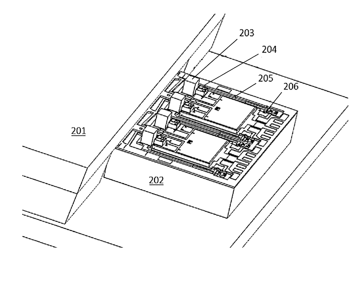
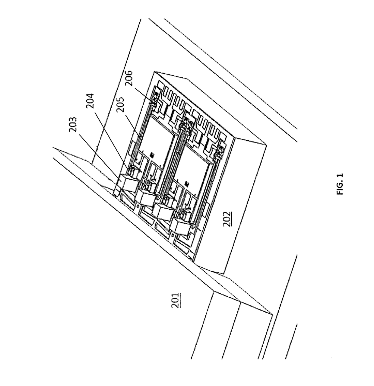
[0013]FIG. 1 shows an optical subassembly that combines four discrete laser diodes into a single-mode output using a Planar Light Circuit (PLC) combiner. The optical subassembly may be part of a MEMs packaging technology for combining lasers into a single fiber output. A PLC chip 201 has four input waveguides (not shown in FIG. 1) and contains a wavelength multiplexer such as an AWG (not shown) with a single output on the other side of the chip (not shown). The assembly contains four lasers 204 that emit light into four lenses 203, one lens per laser. The lens focuses the light and matches the mode to the input waveguides of the PLC 201. The lenses are mounted on a corresponding movable stage built on a silicon chip 202 using silicon MEMS (micro-electro-mechanical systems) techniques. Each movable stage is connected to a lever 205 that magnifies the motion of the lens. At the end of the lever is a heater 206 used to lock down the lever with the lens in the optimal position. The asse...


PUM


Abstract

Light from discrete red, blue, and green lasers are combined into a single output using a planar lightwave circuit (PLC). In some embodiments some light from an output of the PLC is reflected back to the lasers, and in some embodiments the reflected light is primarily of one of the red, green, or blue wavelengths. In some embodiments multiple lasers of slightly differing wavelengths are provided as light sources for some or all of the red, blue, and green light.

Description

BACKGROUND OF THE INVENTION[0001]The present invention relates generally to color display light sources, and more particularly to a light source combiner with laser light sources.[0002]Color displays are often implemented using discrete red, green, and blue (RGB) light sources. These can be lamps, LEDs, or lasers. Lasers are particularly advantageous because they can be combined into a single-mode optical fiber, allowing an effective point RGB source for high-resolution applications. Often the lasers are combined using bulk optics that require complicated alignments and take up a lot of space. These assemblies can be difficult to keep aligned over a wide range of environmental conditions and over life of the assembly.BRIEF SUMMARY OF THE INVENTION[0003]Some embodiments in accordance with various aspects of the invention include a plurality of laser diodes, outputs of the laser diodes combinable to provide different colors in a spectrum of visible light; and a planar lightwave circui...

Claims


Application Information

Patent Timeline
Patent Type & Authority Applications(United States)
IPC IPC(8): G02B6/12G02B6/42H01S5/022
CPCG02B6/12019G02B6/12026G02B6/4204G02B6/4287H01S5/02284H01S5/02251
Inventor HEANUE, JOHNPEZESHKI, BARDIABULTHUIS, HENK
Owner T&S COMM
Why Eureka
Try Eureka