Laser homogenizing coupler device for laser display

A coupling device and laser display technology, which is applied to the coupling of optical waveguides, lasers, and laser components, can solve problems such as transportation difficulties, limited output power, and uneven light intensity distribution, so as to avoid cooling by circulating water and meet Brightness requirements, the effect of eliminating beam speckle

Inactive Publication Date: 2008-03-19
ACAD OF OPTO ELECTRONICS CHINESE ACAD OF SCI
View PDF0 Cites 22 Cited by
  • Summary
  • Abstract
  • Description
  • Claims
  • Application Information

AI Technical Summary

Problems solved by technology

[0005] (1) Due to the limited output power of a single laser, and with the increase of the screen, the brightness of the display screen gradually decreases, it is difficult to meet the brightness requirements of a large-screen laser display; at the same time, for a single laser, the heat dissipation requirements are also very high. It is often necessary to use circulating water for cooling, resulting in a large volume of the entire light source, poor maintenance performance, and difficult transportation, which is very unsuitable for industrialization
[0006] (2) Since the light intensity emitted from the laser obeys the Gaussian distribution, the light intensity distribution is not uniform, so before it is used for laser display, the prior art usually uses optical systems to homogenize its light field, and these optical systems also cause the entire The volume of the light source increases
[0007] (3) Light of the same color is emitted by the same light source. Due to the coherence characteristics of the light source itself, the emitted light interferes with each other to produce speckle, which reduces the resolution of the displayed image and deteriorates the image quality.
In order to eliminate beam speckle, the beam emitted from the laser light source is usually divided into multiple partial beams and these partial beams are time-averaged by periodic movement, which leads to an increase in the size of the display system

Method used


Image

  • Laser homogenizing coupler device for laser display
  • Laser homogenizing coupler device for laser display

Examples


Embodiment 1

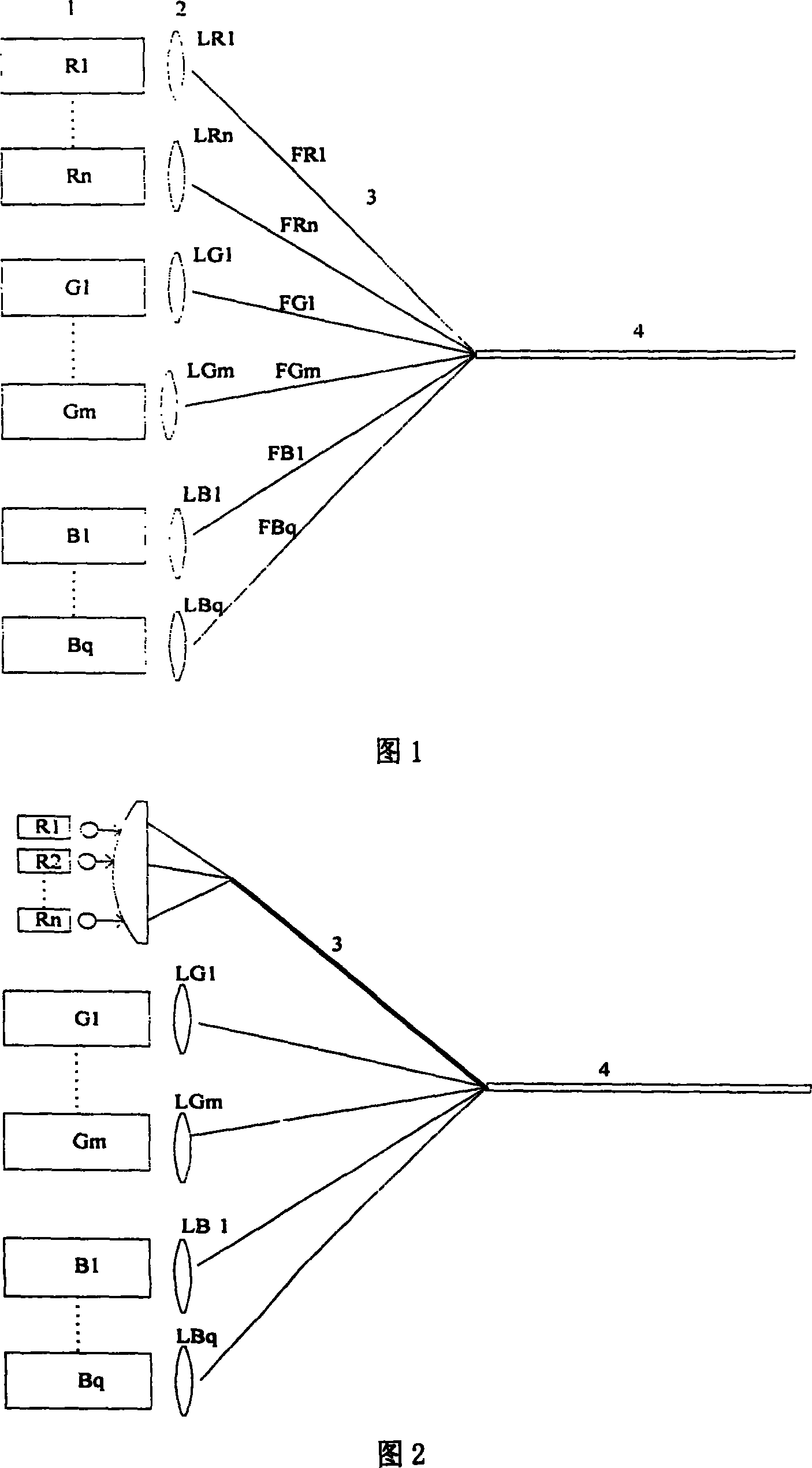
[0032] As shown in Figure 1, the RGB (red, green, blue) three-color laser source 1 of the present embodiment consists of n red lasers (represented by R1~Rn in the figure) and m green lasers (G1~Gm in the figure). ) and q blue lasers (indicated by B1 to Bq in the figure), where n, m, and q are integers greater than or equal to 2, such as n=2, m=3, q=4. Red, green and blue lasers all use solid-state lasers. These solid-state lasers are placed in parallel in the same direction, and the light emitted by the lasers is shaped into parallel light by shaping devices such as cylindrical lenses, ball lenses, or other optical systems for shaping. In the direction perpendicular to the laser emission direction of the red, green and blue lasers, a plurality of converging lenses 2 are respectively placed. In Fig. 1, the converging lenses corresponding to each red solid laser are denoted by LR1~LRn, corresponding to each green The converging lenses of the solid-state lasers are denoted by LG...

Embodiment 2

[0034] As shown in Figure 2, on the basis of Embodiment 1, the red (R) laser light source of this embodiment is composed of (indicated by R1-Rn in the figure) lasers, and the green (G) color and blue (B) laser light sources are respectively It consists of lasers (indicated by G1-Gm and B1-Bq in the figure). Where n, m, and q are integers greater than or equal to 2, such as n=3, m=4, and q=5. The red laser uses a semiconductor laser, and the green and blue lasers use a solid-state laser.

[0035] Since the divergence angle of semiconductor lasers in the vertical direction (about 30°-40°) and the divergence angle in the horizontal direction (about 6°-10°) are very different, collimation and A converging optical system (such as two ball lenses or a self-focusing lens) makes the laser light converge to the optical fiber to realize the coupling of red light, or place these semiconductor lasers in parallel in the same direction as shown in Figure 2, and place each semiconductor las...

Embodiment 3

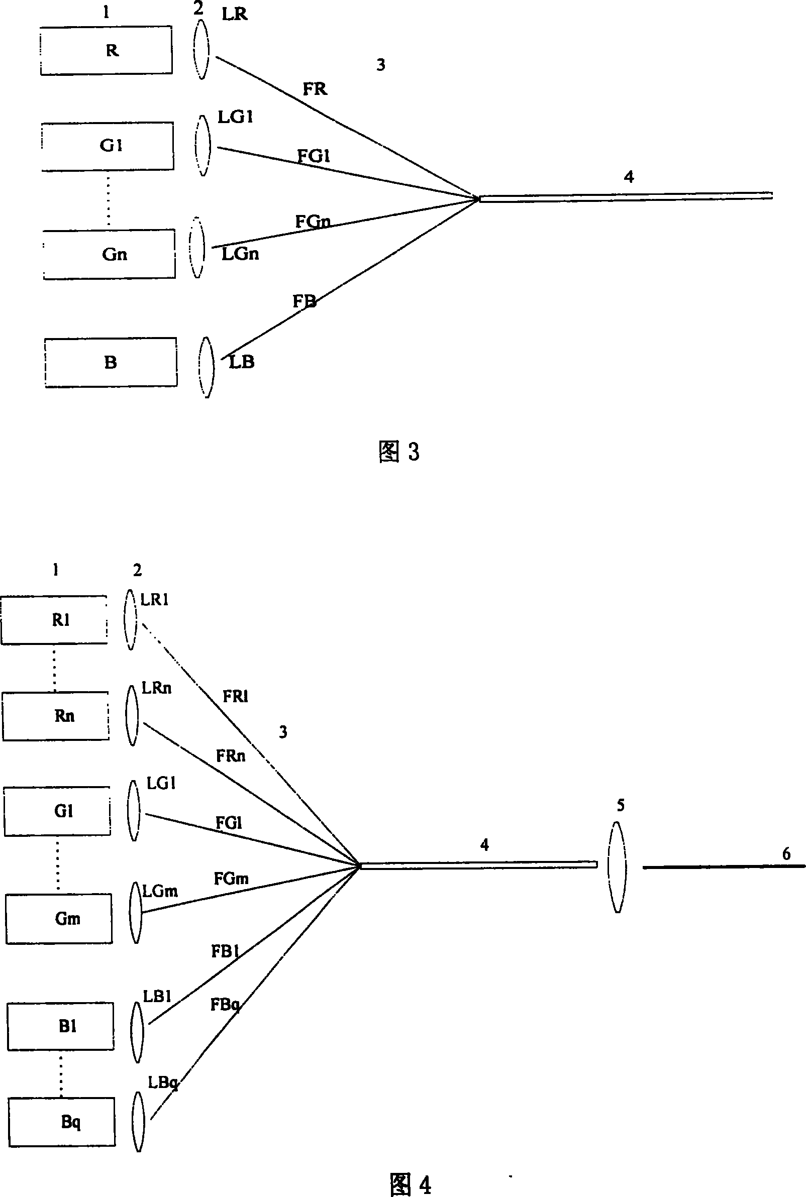
[0038] As shown in FIG. 3 , a schematic diagram of another embodiment of the present invention. Under the same brightness requirements, the smaller the size of the screen, the smaller the required laser power. The speckle phenomenon caused by the interference of the light source is mainly caused by green light. This embodiment adopts the coupling uniformity shown in Figure 3 Optimized device to eliminate the speckle phenomenon of small screen laser display. Both the red and blue laser sources are composed of a single laser (indicated by R and B in Figure 3), and the green laser source is composed of n lasers (indicated by G1-Gn in Figure 3), where n is greater than or equal to 2 An integer, such as n=3. Red, green and blue lasers all use solid-state lasers. Other techniques of this embodiment are the same as those of Embodiment 1.


PUM


Abstract

The present invention discloses a laser equalization coupling device for laser display, and includes a trichromatic laser source and a focusing device. The trichromatic laser source comprises at least one red laser device, at least one green laser device, and at least one blue laser device. The focusing device includes a plurality of coupling optical fibers and a bushing. All coupling optical fibers correspond to the laser devices one-to-one. The laser emitted by the laser device couples and enters into the corresponding coupling optical fiber, and all output ends of the coupling optical fibers are packed in the bushing to form a combined beam of output laser. The present invention can meet the brightness requirement of the big-screen laser display, can reduce the volume of the whole coupling device, and can eliminate the beam speckle.

Description

technical field [0001] The invention relates to a laser homogenization coupling device for laser display, which can meet the power requirements of large-screen laser display and can eliminate speckles generated by laser beams emitted from laser light sources. Background technique [0002] Compared with the existing display technology, laser display has a larger color gamut range, and laser is a line spectrum with high color saturation, which can display the most real and vivid colors in nature. It has become a major development direction in the display field . [0003] In the existing laser display technology, a single laser is widely used as a light source for RGB (red, green and blue) colors, and the emitted light directly enters the projection system. Such as the laser display system of American Color Company. [0004] The deficiencies of prior art are: [0005] (1) Due to the limited output power of a single laser, and with the increase of the screen, the brightness o...

Claims


Application Information

Patent Timeline
Patent Type & Authority Applications(China)
IPC IPC(8): G02B6/42H01S5/00
Inventor 毕勇房涛亓岩郑光王斌成华赵江山
Owner ACAD OF OPTO ELECTRONICS CHINESE ACAD OF SCI
Why Eureka
Try Eureka