Eureka AIR delivers breakthrough ideas for toughest innovation challenges, trusted by R&D personnel around the world.

Single cell of fuel cell

Active Publication Date: 2018-05-10
TOYOTA JIDOSHA KK
View PDF1 Cites 2 Cited by
  • Summary
  • Abstract
  • Description
  • Claims
  • Application Information

AI Technical Summary

Benefits of technology

The patent relates to a single cell of a fuel cell with improved stability and efficiency. The cell has a membrane-electrode assembly and two separators holding the assembly. The separators have uneven channels that are arranged in a way that prevents uneven distribution of contact surfaces and damage to the membrane-electrode assembly. The channels have a pitch that is not an integer, which further reduces the likelihood of misalignment. The plural channels in the region opposite the membrane-electrode assembly can be designed to have different load distribution, reducing uneven application of load and damage to the membrane-electrode assembly. The design also reduces the pressure loss of the reaction gas and improves power generation efficiency.

Problems solved by technology

However, in the cases where positions of the single cells of the adjacent fuel cells are misaligned in an in-plane direction of the single cell of the fuel cell and positions of the adjacent separators are thereby misaligned, uneven distribution of the contact surfaces of the separators and a reduction in an area of the contact surfaces occur, and distribution of the region where the load is supported is changed.
Consequently, such a problem that structures of the fuel cell stack and the single cell of the fuel cell become unstable occurs.
In addition, a difference between distribution of a load applied to the membrane-electrode assembly from one of the separators holding the membrane-electrode assembly and distribution of a load applied to the membrana-lectrode assembly from the other separator is increased, and the load is unevenly applied to one of the surfaces of the membrane-electrode assembly.
Thus, such a problem that the membrane-electrode assembly is possibly damaged occurs.

Method used


Image

  • Single cell of fuel cell
  • Single cell of fuel cell
  • Single cell of fuel cell

Examples


Embodiment Construction

A. Embodiments

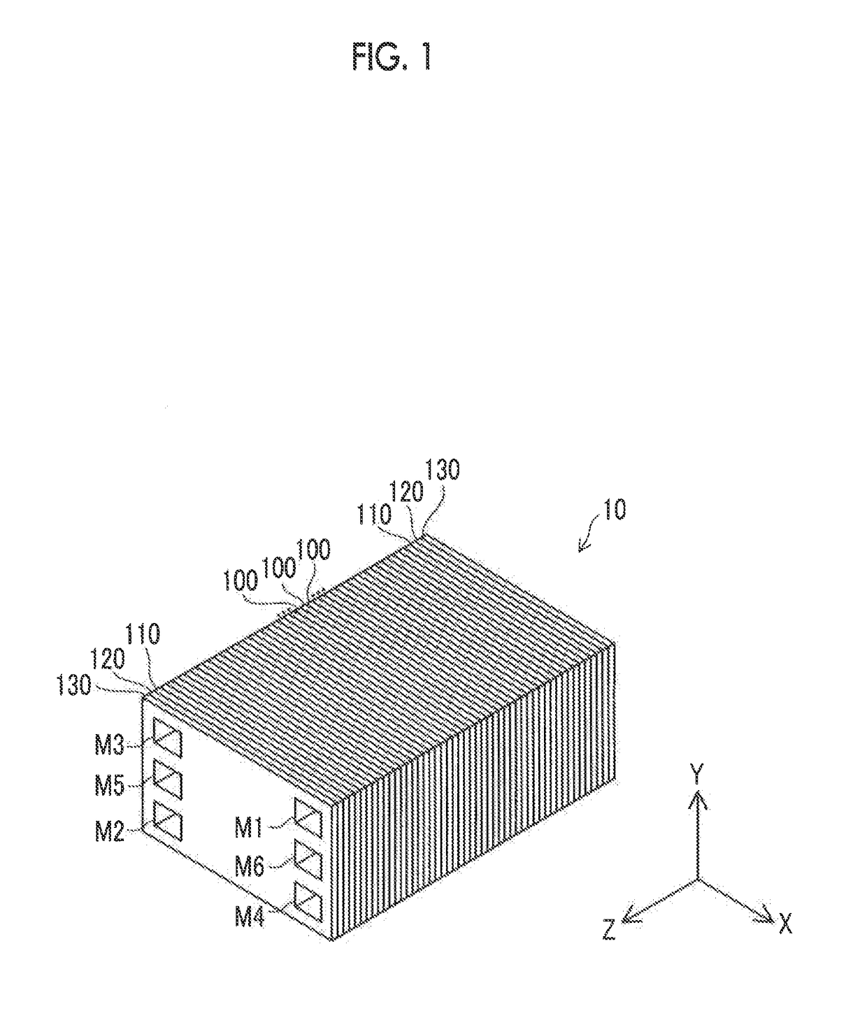
[0030]FIG. 1 is a view that schematically illustrates external appearance of a fuel cell stack 10. In FIG. 1, an X-direction is a longitudinal direction of a fuel cell 100, a Y-direction is a short direction thereof, and a Z-direction is a stacked direction thereof. The same applies to the other drawings.

[0031]The fuel cell stack 10 includes “single cells” (will also be simply referred to as “fuel cells”) 100 of the fuel cell, terminal plates 110, insulation plates 120, and end plates 130. The plural fuel cells 100 are provided, are stacked in the Z-direction, and constitute a stack. The terminal plates 110 are respectively arranged on both sides of the plural stacked fuel cells 100 and are used to take out a voltage and a current from the fuel cells 100. The insulation plates 120 are respectively arranged on outer sides of the terminal plates 110. The end plates 130 are respectively arranged on both sides of the fuel cell stack 10 to fasten the stacked fuel cells 100,...


PUM


Abstract

A single cell of a fuel cell has: a membrane-electrode assembly; and first and second separators holding the membrane-electrode assembly therebetween. The first separator has plural first straight or wavy groove channels that are arranged in parallel to each other in a first in-plane direction. A cross section along the first in-plane direction of each of the plural first groove channels has a first uneven shape. The first uneven shape has a first pitch P1 along the first in-plane direction. The second separator has plural second wavy groove channels that are aligned along the first in-plane direction. A second uneven shape of the plural second groove channels has a second pitch P2 along the first in-plane direction. The first pitch P1 and the second pitch P2 differ from each other, and neither a value of P1 / P2 nor a value of P2 / P1 is an integer.

Description

INCORPORATION BY REFERENCE[0001]The disclosure of Japanese Patent Application No. 2016-218830 filed on Nov. 9, 2016 including the specification, drawings and abstract is incorporated herein by reference in its entirety.BACKGROUND1. Technical Field[0002]The disclosure relates to a single cell of a fuel cell that constitutes a stack, in particular, to a structure of a groove channel in a separator that is included in the single cell of the fuel cell.2. Description of Related Art[0003]A structure of a single cell of a fuel cell is disclosed in Japanese Patent Application Publication No. 2011-119061 (JP 2011-119061 A). In the single cell, a wavy groove channel for reaction gas is formed in each of a separator provided on one electrode side and a separator provided on the other electrode side in an electrolyte / electrode structural body (a membrane-electrode assembly).SUMMARY[0004]When the plural fuel cells described above are stacked to constitute a fuel cell stack, in a separator of the...

Claims


Application Information

Patent Timeline
IPC IPC(8): H01M8/026H01M8/0273H01M8/1004H01M8/1007
CPCH01M8/026H01M8/0273H01M8/1004H01M8/1007H01M8/0263H01M8/1006H01M2008/1095Y02E60/50
Inventor NONOYAMA, NOBUAKIKOBAYASHI, MASAYA
Owner TOYOTA JIDOSHA KK
Why Eureka
Eureka Blog
Learn More