Implantable Lead

a lead and lead technology, applied in the field of implantable lead, can solve the problems of clearer difficulty, and achieve the effect of increasing compression

Active Publication Date: 2018-05-17
BIOTRONIK SE & CO KG
View PDF4 Cites 7 Cited by
  • Summary
  • Abstract
  • Description
  • Claims
  • Application Information

AI Technical Summary

Benefits of technology

[0012]In economical and reliably working structural designs, the sealing and resistance element is a ring made of compressible material that is increasingly compressed as the above-mentioned section with changing diameter passes through it while the means of fixation are being extended. The increasing compression can be achieved, for instance, by clamping the compressible ring between two flange rings on its support—that is, the outer electrode body or the inner part—so that the ring cannot “move out” to the side.

Problems solved by technology

The inventors think that the extension movement should be very easy in the beginning phase, however, clearly more difficult in the end phase.

Method used


Image

  • Implantable Lead
  • Implantable Lead
  • Implantable Lead

Examples


Embodiment Construction

[0029]The following description is of the best mode presently contemplated for carrying out at least one embodiment of the present invention. This description is not to be taken in a limiting sense, but is made merely for the purpose of describing the general principles of the present invention. The scope of the present invention should be determined with reference to the claims.

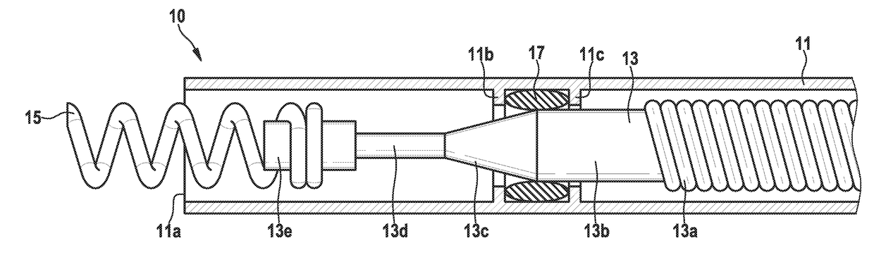
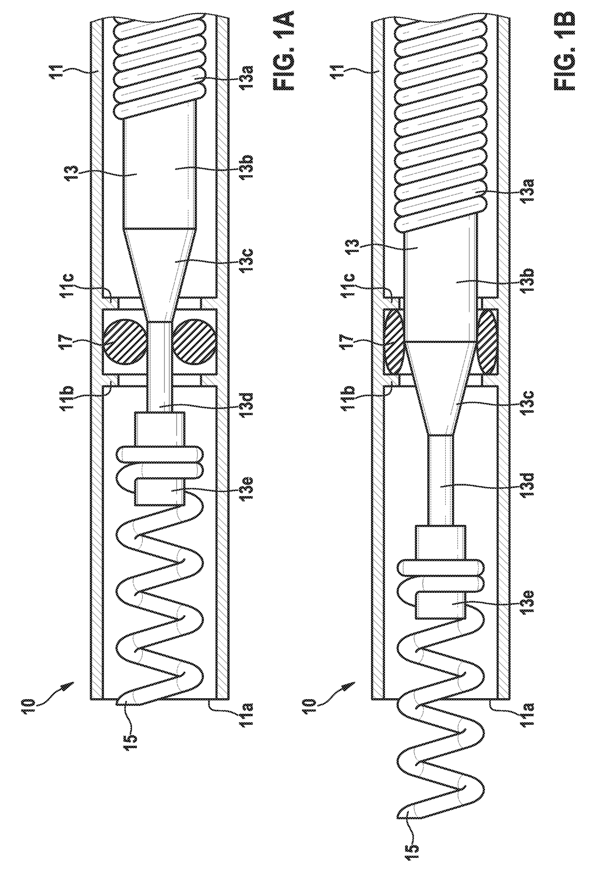
[0030]FIGS. 1A and 1B are schematic longitudinal sections showing the distal end section of an implantable electrode lead 10 in which a rotatably movable inner part 13 is arranged in an essentially hollow, cylindrical electrode body 11. The inner part 13 has, on its distal end, which is adjacent to the free (distal) end 11a of the electrode body 11, a helical screw 15 to fix the lead to body tissue, especially cardiac tissue, of a patient. By having the helical screw 15 interact with an advancing element (not shown), it is possible to realize, at the distal end of the electrode body 11, a screw mechanism tha...


PUM


Abstract

Implantable lead having an electrode body with a free end and an inner part axially movable or rotatably movable with respect to it and an end on which means of fixation are extendable out of the free end by axially displacing the inner part, the inner periphery of the electrode body having an elastically deformable, peripheral, ring or ring segment-shaped, sealing/resistance element fixed to it. The outer periphery of the inner part having a section whose diameter changes (decreases) in the axial direction; this section passes the sealing/resistance element when the inner part is axially displaced. The inner periphery of the electrode body having a section whose diameter changes (decreases) in the axial direction; this section placed so that the sealing/resistance element passes this section when the inner part is axially displaced, the sealing/resistance element increasingly deformed during axial displacement of the inner part and counteracting movement thereof.

Description

CROSS-REFERENCE TO RELATED APPLICATIONS[0001]This patent application claims the benefit of and priority to co-pending European Patent Application No. EP 16198876.1, filed on Nov. 15, 2016 in the European Patent Office, which is hereby incorporated by reference in its entirety.BACKGROUND OF THE INVENTIONField of the Invention[0002]The present invention relates to an implantable lead that has an electrode body with a free end and, arranged in the electrode body, an inner part that is axially movable with respect to it and that has, adjacent to the free end of the electrode body, an end on which there are means of fixation that can be extended out of the free end of the electrode body by axially displacing the inner part, these means of fixation being intended to fix the lead to body tissues in the implanted state.Description of the Related Art[0003]Such leads have long been known and widely used in clinical practice, especially in the form of electrode leads of pacemaker or cardiovert...

Claims


Application Information

Patent Timeline
Patent Type & Authority Applications(United States)
IPC IPC(8): A61N1/05
CPCA61N1/0573A61N1/0565A61N1/057
Inventor TAEUBERT, KERSTINKOLBERG, GERNOT
Owner BIOTRONIK SE & CO KG
Why Eureka
Try Eureka