Treatment delivery control system and method of operation thereof

a control system and treatment technology, applied in the field of solid cancer treatment, can solve the problems of reduced ability to repair damaged dna, death of patients, and special vulnerability to attack on dna

Inactive Publication Date: 2018-05-17
SPOTTS STEPHEN L
View PDF2 Cites 2 Cited by
  • Summary
  • Abstract
  • Description
  • Claims
  • Application Information

AI Technical Summary

Problems solved by technology

These particles damage the DNA of cells, ultimately causing their death.
Cancerous cells, because of their high rate of division and their reduced ability to repair damaged DNA, are particularly vulnerable to attack on their DNA.

Method used


Image

  • Treatment delivery control system and method of operation thereof
  • Treatment delivery control system and method of operation thereof
  • Treatment delivery control system and method of operation thereof

Examples


Embodiment Construction

[0070]The invention relates generally to a charged particle treatment delivery control system and method of operation therefor.

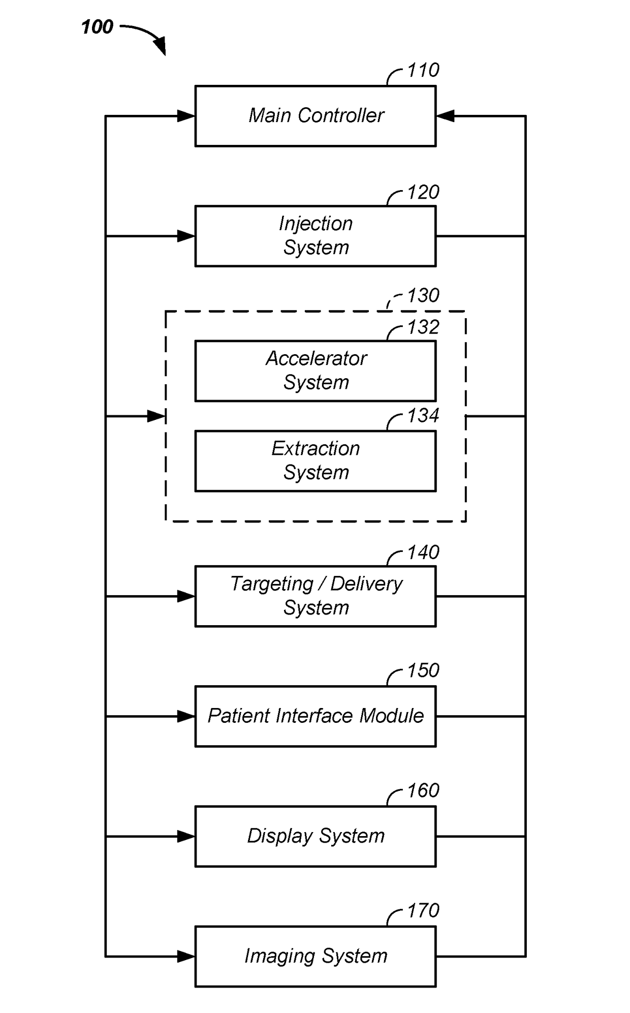
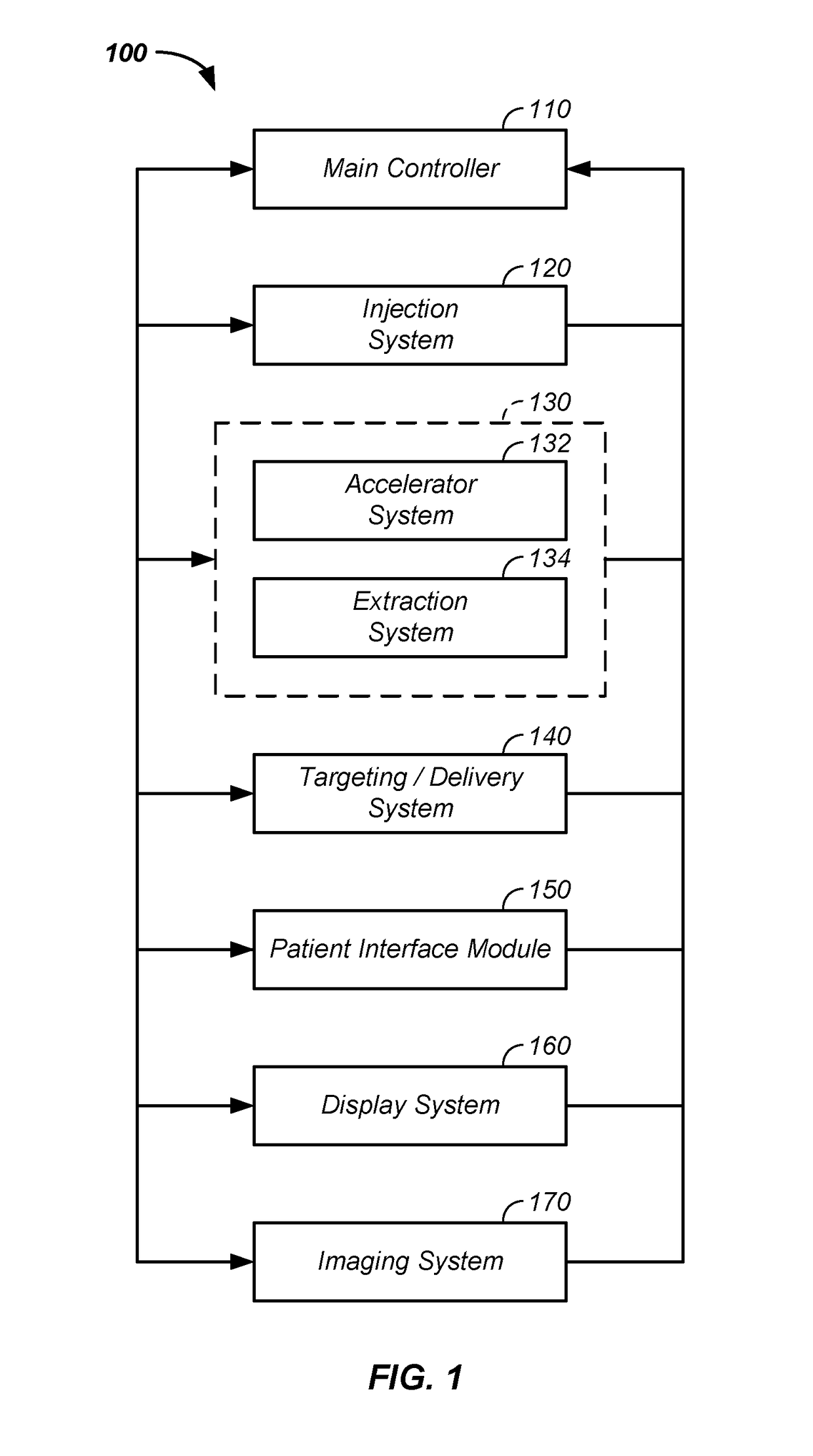
[0071]In one embodiment, a treatment delivery control system (TDCS) or main controller is used to control multiple aspects of the cancer therapy system, including one or more of: an imaging system, such as a CT or PET; a positioner, such as a couch or patient interface module; an injector or injection system; a radio-frequency quadrupole system; a ring accelerator or synchrotron; an extraction system; an irradiation plan; and a display system. The TDCS is preferably a control system for automated cancer therapy once the patient is positioned. The TDCS integrates output of one or more of the below described cancer therapy system elements with inputs of one or more of the below described cancer therapy system elements. More generally, the TDCS controls or manages input and / or output of imaging, an irradiation plan, and charged particle delivery.

[0072]In anothe...


PUM


Abstract

The invention relates to a method and apparatus for control of a charged particle cancer therapy system. A treatment delivery control system is used to directly control multiple subsystems of the cancer therapy system without direct communication between selected subsystems, which enhances safety, simplifies quality assurance and quality control, and facilitates programming. For example, the treatment delivery control system directly controls one or more of: an imaging system, a positioning system, an injection system, a radio-frequency quadrupole system, a ring accelerator or synchrotron, an extraction system, a beam line, an irradiation nozzle, a gantry, a display system, a targeting system, and a verification system. Generally, the control system integrates subsystems and / or integrates output of one or more of the above described cancer therapy system elements with inputs of one or more of the above described cancer therapy system elements.

Description

CROSS-REFERENCES TO RELATED APPLICATIONS[0001]This application is a continuation of U.S. patent application Ser. No. 15 / 152,479 filed May 11, 2016, which:[0002]is a continuation-in-part of U.S. patent application Ser. No. 14 / 216,788 filed Mar. 17, 2014,[0003]which is a continuation-in-part of U.S. patent application Ser. No. 13 / 087,096 filed Apr. 14, 2011, which claims benefit of U.S. provisional patent application No. 61 / 324,776 filed Apr. 16, 2010; and[0004]is a continuation-in-part of U.S. patent application Ser. No. 13 / 788,890 filed Mar. 7, 2013;[0005]is a continuation-in-part of U.S. patent application Ser. No. 14 / 952,817 filed Nov. 25, 2015 is a continuation-in-part of U.S. patent application Ser. No. 14 / 293,861 filed Jun. 2, 2014, which is a continuation-in-part of U.S. patent application Ser. No. 12 / 985,039 filed Jan. 5, 2011, which claims the benefit of U.S. provisional patent application No. 61 / 324,776, filed Apr. 16, 2010;[0006]is a continuation-in-part of U.S. patent app...

Claims


Application Information

Patent Timeline
Patent Type & Authority Applications(United States)
IPC IPC(8): A61N5/10G21K1/087G21K5/04A61B6/03G21K1/093H01J35/14
CPCA61N2005/1087A61N5/1067A61B6/03A61N5/1077H01J35/14G21K1/087A61N2005/1074A61N5/1044G21K5/04G21K1/093A61N5/107A61N5/1082A61N2005/1097H01J35/147
Inventor SPOTTS, STEPHEN L.
Owner SPOTTS STEPHEN L
Why Eureka
Try Eureka