Vessel propulsion apparatus and vessel including the same

Active Publication Date: 2018-05-17
YAMAHA MOTOR CO LTD
View PDF0 Cites 5 Cited by
  • Summary
  • Abstract
  • Description
  • Claims
  • Application Information

AI Technical Summary

Benefits of technology

[0018]With this arrangement, even when an output command is low, stable rotation of the propeller is obtained, and in response to an output comma

Problems solved by technology

However, when the rim rotates at a low speed, the water flow in the gap between the fluid bearing and the rim is insufficient, so that sufficient water lubrication cannot be obtained, and

Method used


Image

  • Vessel propulsion apparatus and vessel including the same
  • Vessel propulsion apparatus and vessel including the same
  • Vessel propulsion apparatus and vessel including the same

Examples


Embodiment Construction

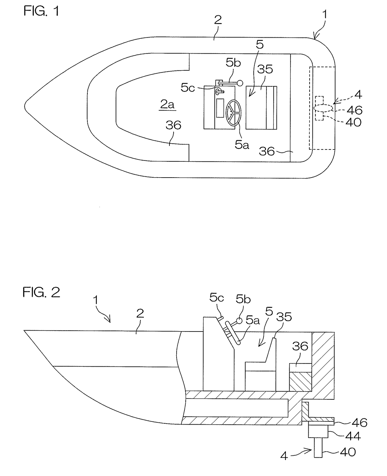
[0029]FIG. 1 is a schematic plan view to describe an example of a vessel 1 according to a preferred embodiment of the present invention, and FIG. 2 is a side view of the same, partially showing a section thereof. The vessel 1 includes a hull 2 and an electric propulsion unit 4 provided on the hull 2. A cockpit 5 is disposed inside a cabin 2a compartmented inside the hull 2. A steering wheel 5a, a shift lever 5b, and a joystick 5c, etc., are disposed in the cockpit 5. A vessel operator seat 35 is disposed in the cockpit 5. A seat 36 for occupants is disposed inside the cabin 2a.

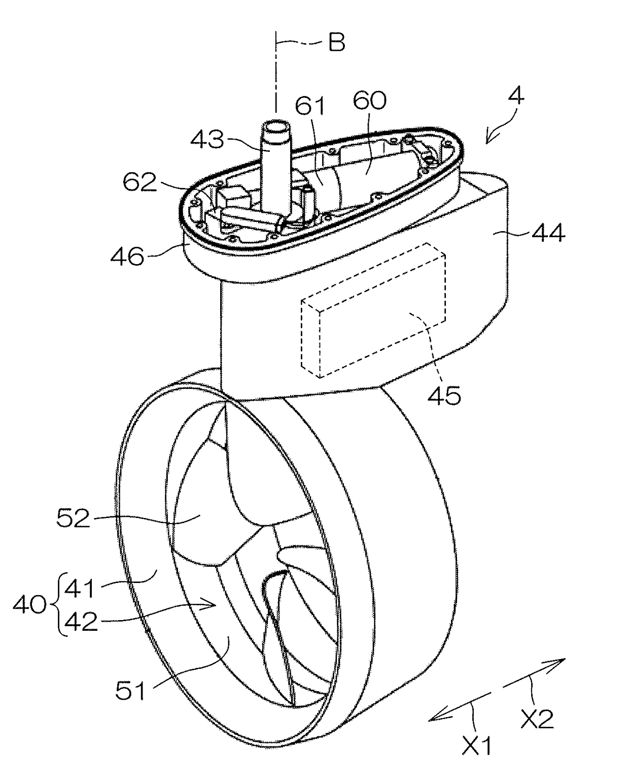
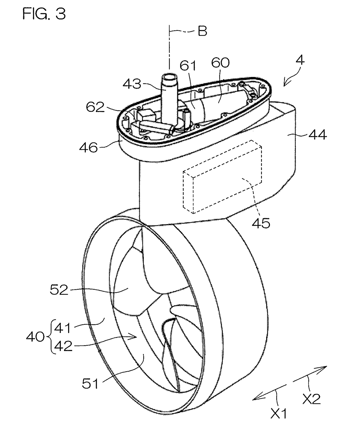
[0030]FIG. 3 is a perspective view to describe an example of the electric propulsion unit, and FIG. 4 is a longitudinal sectional view of the same. The electric propulsion unit 4 includes a cylindrical or substantially cylindrical duct 41, a propeller 42, a steering shaft 43, a casing 44, a motor controller 45, and a turning mechanism 46. The duct 41 includes a stator 47. The duct 41 and the propeller 42 defi...


PUM


Abstract

A vessel propulsion apparatus includes a cylindrical duct including a stator and a propeller. The propeller includes a rim including a rotor disposed at a position facing the stator and defining an electric motor in combination with the stator, and blades on an inner side in a radial direction of the rim. A fluid bearing is provided on the duct and defines a gap into which surrounding water is introduced between the fluid bearing and the rim, and is water-lubricated with respect to the rim due to water introduced into the gap from the surroundings. The vessel propulsion apparatus further includes a motor controller that drives the electric motor by rotation speed control in a rotation speed control region in which an output command is not more than a predetermined value, and drives the electric motor by torque control in a torque control region in which an output command is more than the predetermined value.

Description

CROSS REFERENCE TO RELATED APPLICATIONS[0001]This application claims the benefit of priority to Japanese Patent Application No. 2016-221861 filed on Nov. 14, 2016. The entire contents of this application are hereby incorporated herein by reference.BACKGROUND OF THE INVENTION1. Field of the Invention[0002]The present invention relates to a vessel propulsion apparatus that generates a propulsive force by using an electric motor as a drive source, and a vessel including the same.2. Description of the Related Arts[0003]United States Patent Application Publication No. 2016 / 0185431 A1 discloses an electric propulsion unit including a cylindrical duct that functions as a stator and a rim that functions as a rotor rotatable relative to the duct. The rim includes a plurality of blades inside. The stator and the rotor constitute an electric motor. By driving this electric motor, the rim rotates, and blades provided in the rim generate a propulsive force.[0004]A recess is defined annularly on ...

Claims


Application Information

Patent Timeline
IPC IPC(8): B63H1/16B63H23/24B63H21/17B63H25/42B63H21/21
CPCB63H1/16B63H23/24B63H21/17B63H25/42B63H21/213B63H2001/165B63H2021/216B63H21/21B63H23/326B63H2023/005
Inventor SUZUKI, TAKAYOSHIYAMAGUCHI, KOHEI
Owner YAMAHA MOTOR CO LTD
Why Eureka
Try Eureka