Check patentability & draft patents in minutes with Patsnap Eureka AI!

Parallel reservoir simulation with accelerated aquifer calculation

Active Publication Date: 2018-05-17
SAUDI ARABIAN OIL CO
View PDF2 Cites 12 Cited by
  • Summary
  • Abstract
  • Description
  • Claims
  • Application Information

AI Technical Summary

Benefits of technology

The present invention provides a new and improved machine and method for simulating the reservoir simulation measures of a subsurface reservoir with a hydrocarbon region and an aquifer region. The machine includes a plurality of processor nodes with parallel computer cores operating in parallel, which are assigned to processing sub-domains. The sub-domains include a parallel input processing grid sub-domain, an unstructured graph and connection factor sub-domain, and a simulation processing sub-domain. The method involves determining the presence of vertical columns of cells in the aquifer region and grouping them into connected grid blocks. Load balanced domain partitioning is performed, and transmissibilities between cells are generated. The reservoir simulation of the cells of the hydrocarbon region is performed to determine pressures and pore volumes. The aquifer region is then populated with the determined pressures and pore volumes based on the determined pressures. The new invention provides a more efficient and effective tool for simulating the reservoir simulation measures.

Problems solved by technology

For models which include large aquifer regions, a significant fraction of the computational expense can be in the modeling of the water movement in the aquifer.
This has led to reduced grid resolution.
The more aggressive the coarsening, the poorer the match would be comparing to the original model.
Another prior-art technique, which was usually even more inaccurate, has been to trim the aquifer cells and replace them with an analytic aquifer model.
This approach is too inaccurate and inappropriate in modern simulation practice whenever model data is available.
For modern reservoir simulation, this analytical model is too inaccurate to correctly represent the variable strength of the aquifer across the reservoir boundaries.

Method used


Image

  • Parallel reservoir simulation with accelerated aquifer calculation
  • Parallel reservoir simulation with accelerated aquifer calculation
  • Parallel reservoir simulation with accelerated aquifer calculation

Examples


Embodiment Construction

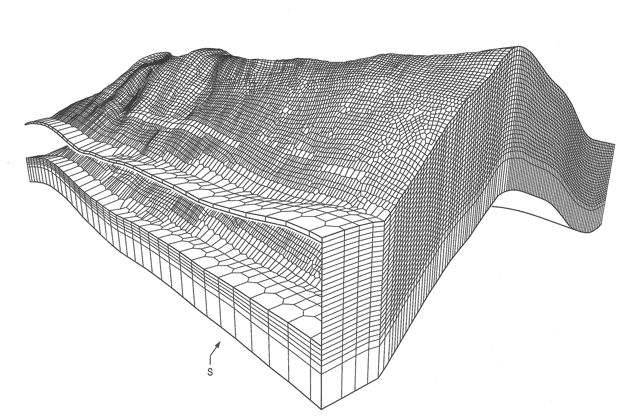
[0033]For the recovery of oil and gas from subterranean reservoirs, wellbores are drilled into these formations for the recovery of hydrocarbon fluid. During the recovery process, fluids such as water and / or gas are injected into the injector wells and the fluid mixture in the pore space is produced from the producer wells. In order to predict the future performance of these reservoirs and to evaluate alternative development plans, reservoir simulators are used to run simulation models.

[0034]According to the present invention, time required for reservoir simulators to produce models of simulated reservoir production measures of interest is reduced. The reservoir production measures indicate reservoir behavior in the form of simulated reservoir fluid pressures and flows. Example of reservoir pressure, reservoir production measures, transmissibilities, fluid produced rate, oil rate, water rate, water cut and average pressure. These models are first calibrated with a history matching s...


PUM


Abstract

Reservoir simulation for simulation models which include a large edge aquifer region is provided with a speed up in processing reducing computer processing time. Connected aquifer grid cells in a vertical column are amalgamated to reduce the total number of active cells in the solution phase. The fine grid property data is maintained for computing distributed 3D graph, and connection factors (transmissibilities), as well as pore volume and compressibility calculation of coarsened aquifer cells during nonlinear solution phase. Since the work load in the solution phase is proportional to the total number of active cells, a significant speedup in simulation time is provided. The aquifer fine grid pressures are computed using vertical equilibrium treatment of hydraulic potential inside an amalgamated aquifer coarse cell.

Description

BACKGROUND OF THE INVENTION1. Field of the Invention[0001]The present invention relates to computerized simulation of hydrocarbon reservoirs, and more particularly to parallel reservoir simulation with accelerated aquifer calculation for a hydrocarbon reservoir surrounded by peripheral aquifer.2. Description of the Related Art[0002]For many current reservoir simulation models, there is generally a large portion of grids being aquifer cells. Computational resources are required to be spent to solve for the grids in the aquifer. Reservoir simulation at present, so far as is known, has treated the aquifer grid cells in the same way as the hydrocarbon bearing grid cells in the reservoir. Aquifer grid coarsening has been used in some cases to save computation time.[0003]Current art reservoir simulation practice treats the grid cells in aquifer regions of the model in the same way as the hydrocarbon bearing regions. This is necessary as hydrocarbon can be inadvertently pushed into the aqu...

Claims


Application Information

Patent Timeline
IPC IPC(8): G06F17/50E21B41/00E21B43/16
CPCG06F17/5018G06F2217/16E21B43/16E21B41/0092G01V11/005E21B41/00G01V20/00G06F30/23G06F2111/10
Inventor FUNG, LARRY SIU-KUENDU, SHOUHONG
Owner SAUDI ARABIAN OIL CO
Features
  • R&D
  • Intellectual Property
  • Life Sciences
  • Materials
  • Tech Scout
  • Unparalleled Data Quality
  • Higher Quality Content
  • 60% Fewer Hallucinations
Learn More