

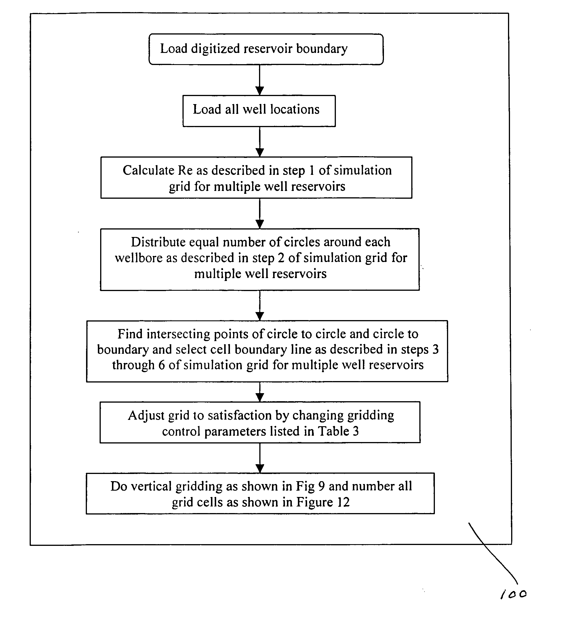
Method for producing full field radial grid for hydrocarbon reservoir simulation
a hydrocarbon reservoir and simulation method technology, applied in seismology for waterlogging, borehole/well accessories, instruments, etc., can solve the problems of no such radial gridding method for multiple well simulation problems, tedious process, and complex simulators of the past, and achieve the effect of facilitating the simulation work flow for engineers
- Summary
- Abstract
- Description
- Claims
- Application Information
AI Technical Summary
Benefits of technology
Problems solved by technology
Method used
Image

Examples
Embodiment Construction
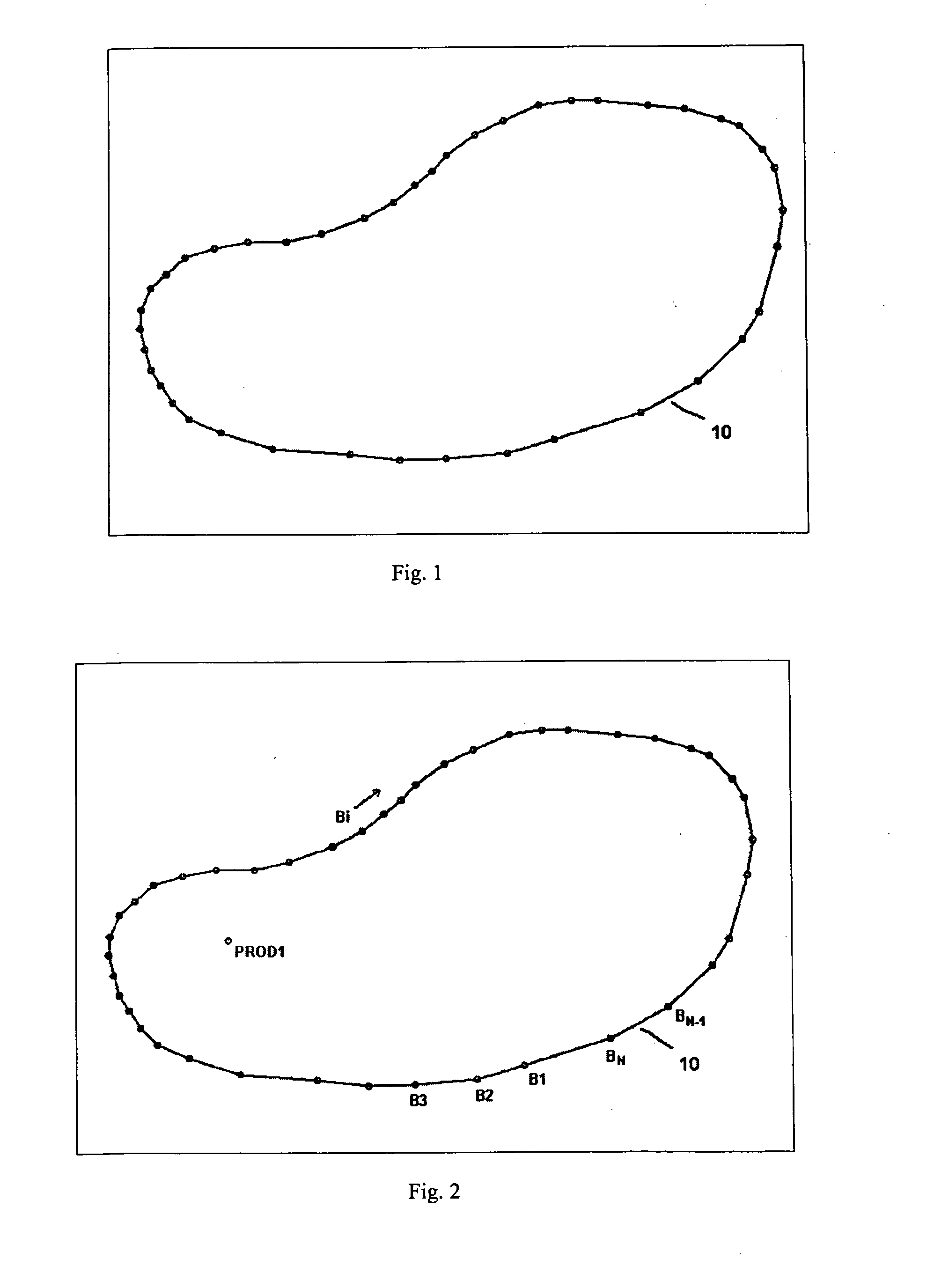
Simulation Grid for Single Well Reservoir FIG. 1 is a top view of a schematic reservoir boundary 10. A reservoir boundary 10 can be created by digitizing paper maps or by exporting contours from a number of geological mapping programs. The boundary 10 can be presented by a reservoir modeling program and displayed on a computer monitor. The reservoir boundary 10 should cover oil and gas accumulative subterranean formations of interest and the surrounding aquifers. If the influence of aquifers is sufficiently considered in the reservoir map, the effect of the fluid exchanges between the enclosed reservoir and the outside regions is not significant to the predicted reservoir and well behaviors, and the reservoir boundary can be considered as impermeable. With the reservoir modeling according to the gridding of this invention, it is assumed that there is no fluid flow into and out of the reservoir boundary.
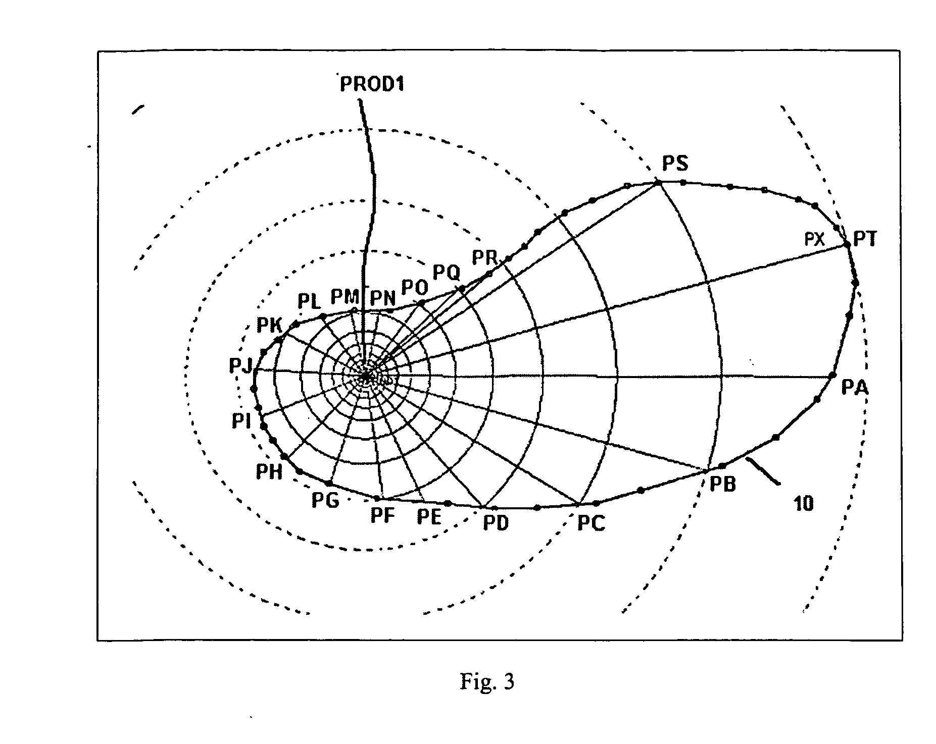
FIG. 2 shows a production well PROD1 that is placed within the reservoir bounda...
PUM
 Abstract
Description
Claims
Application Information