Eccentric support grid for nuclear fuel assembly

a support grid and nuclear fuel technology, applied in nuclear elements, nuclear engineering problems, greenhouse gas reduction, etc., can solve the problems of increasing the amount of force/pressure, reducing the effect of spring structure, and reducing the stress of spring structure, so as to reduce the effect of force/pressure and reduce the effect of stress

Inactive Publication Date: 2006-10-05
WESTINGHOUSE ELECTRIC CORP
View PDF27 Cites 38 Cited by
  • Summary
  • Abstract
  • Description
  • Claims
  • Application Information

AI Technical Summary

Benefits of technology

[0012] In addition to a lower stress, the design of the present invention is less susceptible to operational effects. That is, effects such as irradiation creep, which is dependent upon the amount of stress, has a reduced effect due to the reduced stress. Accordingly, the time period before a space develops between the support grid and the fuel rod is extended, possibly indefinitely. That is, a gap between the fuel rod and the support structure may never occur. Thus, the wear due to fretting is reduced and the useful life of the fuel rod is extended.

Problems solved by technology

A common problem in the PWR fuel industry is vibration of the fuel rod / support system as a natural response to coolant flow.
This phenomenon is manifested as grid-to-rod fretting, which can ultimately lead to a breach in the fuel rod cladding and leakage of nuclear fuel material into the coolant.
This amount of force / pressure creates a significant stress in the spring structure.
The disadvantage to this type of structure is that irradiation and thermal effects alter the shape of the support grid allowing for a reduction in the lateral force applied to the fuel rod.
That is, operational effects cause the springs to relax, the support grid to grow, and the fuel rod to shrink.
The increased fretting reduces the operational life of the fuel rod.

Method used


Image

  • Eccentric support grid for nuclear fuel assembly
  • Eccentric support grid for nuclear fuel assembly
  • Eccentric support grid for nuclear fuel assembly

Examples


Embodiment Construction

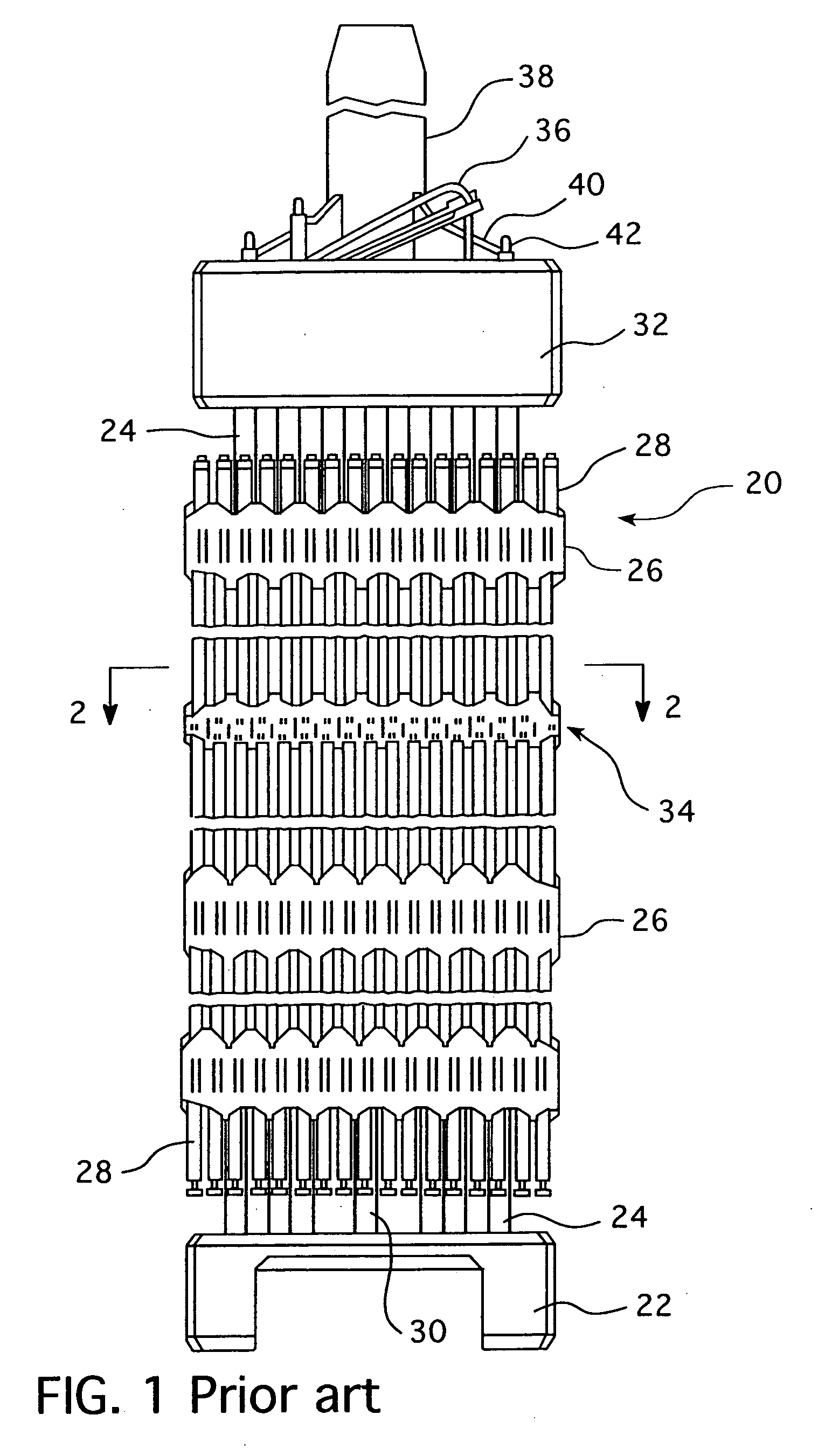
[0020] As shown in FIG. 1, a fuel assembly 20 for a nuclear reactor is disposed in a water vessel (not shown) having an inlet at the bottom and an outlet at the top. The fuel assembly 20 comprises a lower end structure or bottom nozzle 22 for supporting the fuel assembly 20 on the lower core plate (not shown) in the core region of a reactor (not shown); a number of longitudinally extending control rod guide tubes, or thimbles 24, projecting upwardly from the bottom nozzle 22; a plurality of transverse support grids 26 axially spaced along the guide thimbles 24; an organized array of elongated fuel rods 28 transversely spaced and supported by the grids 26; an instrumentation tube 30 located in the center of the assembly; and an upper end structure or top nozzle 32 attached to the upper ends of the guide thimbles 24, in a conventional manner, to form an integral assembly capable of being conventionally handled without damaging the assembly components. The bottom nozzle 22 and the top ...


PUM


Abstract

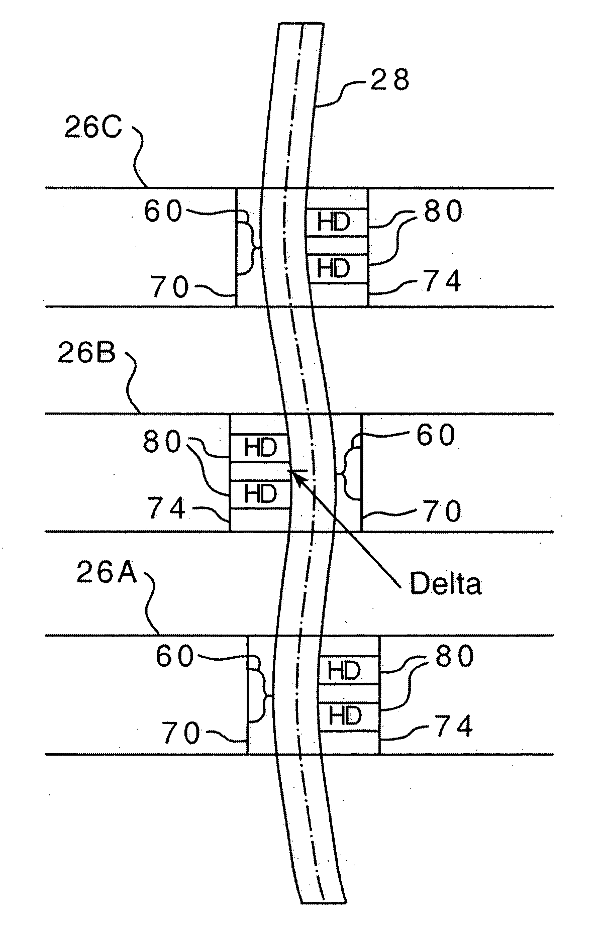
In a nuclear reactor fuel assembly structured to support at least one non-linear fuel rod, the nuclear reactor fuel assembly includes at least two support grids, a first support grid and a second support grid structured to support at least one fuel rod in a non-linear shape. Each support grid has a plurality of generally square cells and wherein the cells on the first support grid and the second support grid are generally vertically aligned. Each cell has a first side, a second side, a third side, and a fourth side. Each cell further has protrusions extending from each the cell sides, wherein the protrusions are selected from the group including a spring, a dimple or an extended dimple. A spring is always disposed opposite of a dimple or an extended dimple. The first support grid includes at least one cell having an extended dimple extending from at least one cell side. The second support grid includes at least one cell aligned with the first support grid at least one cell having an extended dimple, wherein the second support grid cell has an extended dimple extending from a cell side other than cell side having an extended dimple on the first support grid. Thus, the extended dimples cause the fuel rod to be deformed.

Description

BACKGROUND OF THE INVENTION [0001] 1. Field of the Invention [0002] The present invention relates to nuclear reactor fuel assemblies and more particularly to a nuclear reactor fuel assembly wherein the support grids have dimples with an increased height that causes the fuel rod to assume a non-linear shape. [0003] 2. Description of the Prior Art [0004] In a typical pressurized water reactor (PWR), the reactor core is comprised of a large number of generally vertically, elongated fuel assemblies. The fuel assemblies include a frame assembly structured to support a plurality of fuel rods. The fuel assembly includes a top nozzle, a bottom nozzle, a plurality of support grids, intermediate flow mixing grids, and a plurality of thimble tubes. The support grids are attached to the plurality of elongated thimble tubes which extend vertically between the top and bottom nozzles. The thimble tubes typically receive control rods, plugging devices, or instrumentation therein. A fuel rod include...

Claims


Application Information

Patent Timeline
Patent Type & Authority Applications(United States)
IPC IPC(8): G21C3/32
CPCG21C3/322G21C3/356G21Y2002/101Y02E30/38G21Y2002/304G21Y2004/30G21Y2002/206Y02E30/30
Inventor ALESHIN, YURIY A.SPARROW, JAMES A.
Owner WESTINGHOUSE ELECTRIC CORP
Why Eureka
Try Eureka