
Distal Radioulnar Joint Prosthesis and Method of Use

a radioulnar joint and prosthesis technology, applied in the field of medical devices, can solve the problems of patients unable to reach the bone, pain and dysfunction, and patients can become debilitated and seek medical attention, and achieve the effect of maximizing the contact between the implant and the bon

Active Publication Date: 2018-05-24
MAYO FOUND FOR MEDICAL EDUCATION & RES
View PDF6 Cites 2 Cited by
  • Summary
  • Abstract
  • Description
  • Claims
  • Application Information

AI Technical Summary

Benefits of technology

The present invention provides a joint prosthesis that preserves as many ligaments as possible, utilizing articulating components. The device includes an ulnar component with a stem, collar, and shell, as well as a radial component with a plate and hemispherical ball for articulation with the ulnar component. The motion liner interface serves as a boundary for the interaction of the components. The invention optimizes tension and stability features of the joint, and provides customization options for the collar and attachment to the radius. The technical effect of the invention is improved outcomes for joint replacement procedures.

Problems solved by technology

The movement and rotation of these bones enabled by support from the ligaments allows humans to open doors, turn screwdrivers, and many other common daily activities, Like any other joint in the body, the DUI can become significantly damaged through traumatic or degenerative destruction.
Pain and dysfunction often follows any biomechanical disruption and patients eventually become debilitated and seek medical attention.
Historically, this problem was treated with removing half of the joint and not restoring any anatomical structure, limiting the range of motion.
Additionally, the current implants do not have the correct amount of constraint in their designs or require extremely precise alignment in order to provide proper motion.
This causes problems with insertion of the prosthetic implant as well as fixation and therefore long-term survival and loosening.

Method used


Image

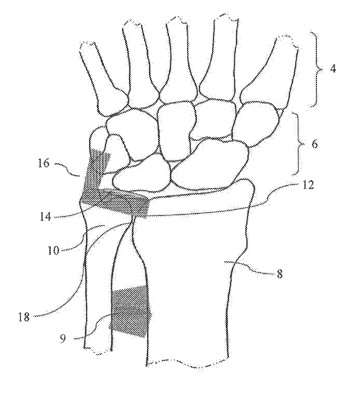
  • Distal Radioulnar Joint Prosthesis and Method of Use
  • Distal Radioulnar Joint Prosthesis and Method of Use
  • Distal Radioulnar Joint Prosthesis and Method of Use

Examples


Embodiment Construction

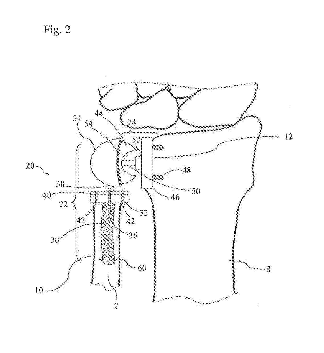
[0031]FIG. 2 illustrates an exemplary distal radioulnar joint (DRUJ) prosthesis that has been implanted in accordance with the present invention. The DRUJ prosthesis 20 generally includes an ulnar component 22 and a radial component 24. The ulnar component 22 includes a stem 30, a collar 32, and a shell 34. The stem 30 has a central set screw 36, The set screw 36 serves as the connector for the stem 30, collar 32, and shell 34. The shell 34 has a shaft 38 that connects the shell 34 to the shell base 40 that is capable of receiving the set screw 36 and coupling to the collar 32. The shell base 40 is attached to the collar 32 by screws 42. The shell 34 allows for coupling with the radial component 24. The radial component 24 includes a hemispherical ball 44 and a plate 46. The plate 46 is secured to the radius 8 at the sigmoid notch 12 via bone screws 48, The hemispherical ball 44 has a rod 50 that couples to a peg 52 on the plate 46. The hemispherical ball 44 couples with the shell 3...


PUM


Abstract

A distal radioulnar joint prosthesis for replacing the distal radioulnar joint and a method for its implantation is provided. Such a device includes an ulnar component, a radial component, and a motion liner. The ulnar component includes a stem, a collar, and a shell. The radial component includes a hemispherical ball and plate. The hemispherical ball of the radial component is secured with the radial plate and articulates with the ulnar shell via the motion liner. The prosthesis is designed to more accurately replicate the biomechanics of the distal wrist than currently used implants.

Description

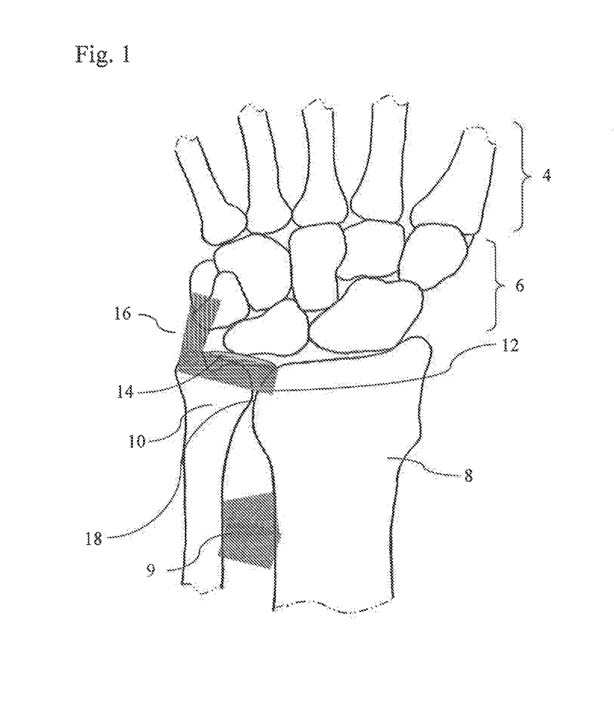
CROSS-REFERENCES TO RELATED APPLICATIONS[0001]This application claims priority to U.S. patent application Ser. No. 62 / 155,518 filed May 1, 2015.STATEMENT REGARDING FEDERALLY SPONSORED RESEARCH[0002]Not Applicable.FIELD OF THE INVENTION[0003]The field of the invention is medical devices and methods for their use. More particularly, the invention relates to a prosthesis for a distal radioulnar joint and methods for its use.BACKGROUND OF THE INVENTION[0004]The distal radioulnar joint (DRUJ) is an essential portion of the wrist that allows rotation or supination and pronation of the forearm. With reference to FIG. 1, the dorsal side of the bone structure of a patient's left proximal metacarpals 4 and carpals 6 is illustrated in conjunction with the radius 8 and the ulna 10. The radius 8 articulates in pronation and supination on the distal head of the ulna 10 at the sigmoid notch 12. The ulna 10, a slightly bowed bone linked to the wrist, translates dorsal-palmarly to accept the modestl...

Claims


Application Information

Patent Timeline
Patent Type & Authority Applications(United States)
IPC IPC(8): A61F2/42
CPCA61F2/4261A61F2002/30331A61F2002/4269A61F2002/30433A61F2002/3055A61F2002/30616A61F2002/30649
Inventor KAKAR, SANJEEVBABB, AARON C.
Owner MAYO FOUND FOR MEDICAL EDUCATION & RES
Learn More